Offset multiaxial or polyaxial screw, system and assembly

a multi-axial or poly-axial screw technology, applied in the field of screw, can solve the problem of difficult to get a “favorable angle” of the retainer relative to the screw head, and achieve the effect of extending the range of motion

Active Publication Date: 2009-06-25
X SPINE SYST
View PDF79 Cites 119 Cited by
  • Summary
  • Abstract
  • Description
  • Claims
  • Application Information

AI Technical Summary

Benefits of technology

[0009]It is therefore, an object of the invention to provide a poly

Problems solved by technology

It was difficult to get a “favorable angle”

Method used


Image

  • Offset multiaxial or polyaxial screw, system and assembly
  • Offset multiaxial or polyaxial screw, system and assembly
  • Offset multiaxial or polyaxial screw, system and assembly

Examples


Embodiment Construction

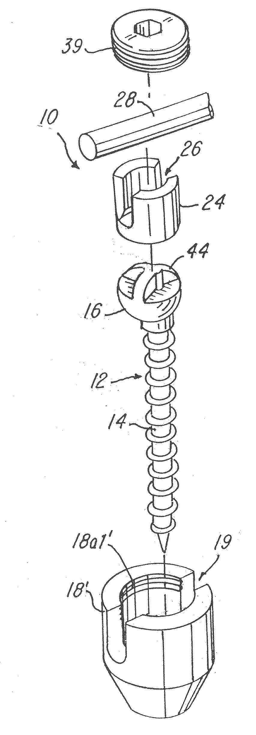
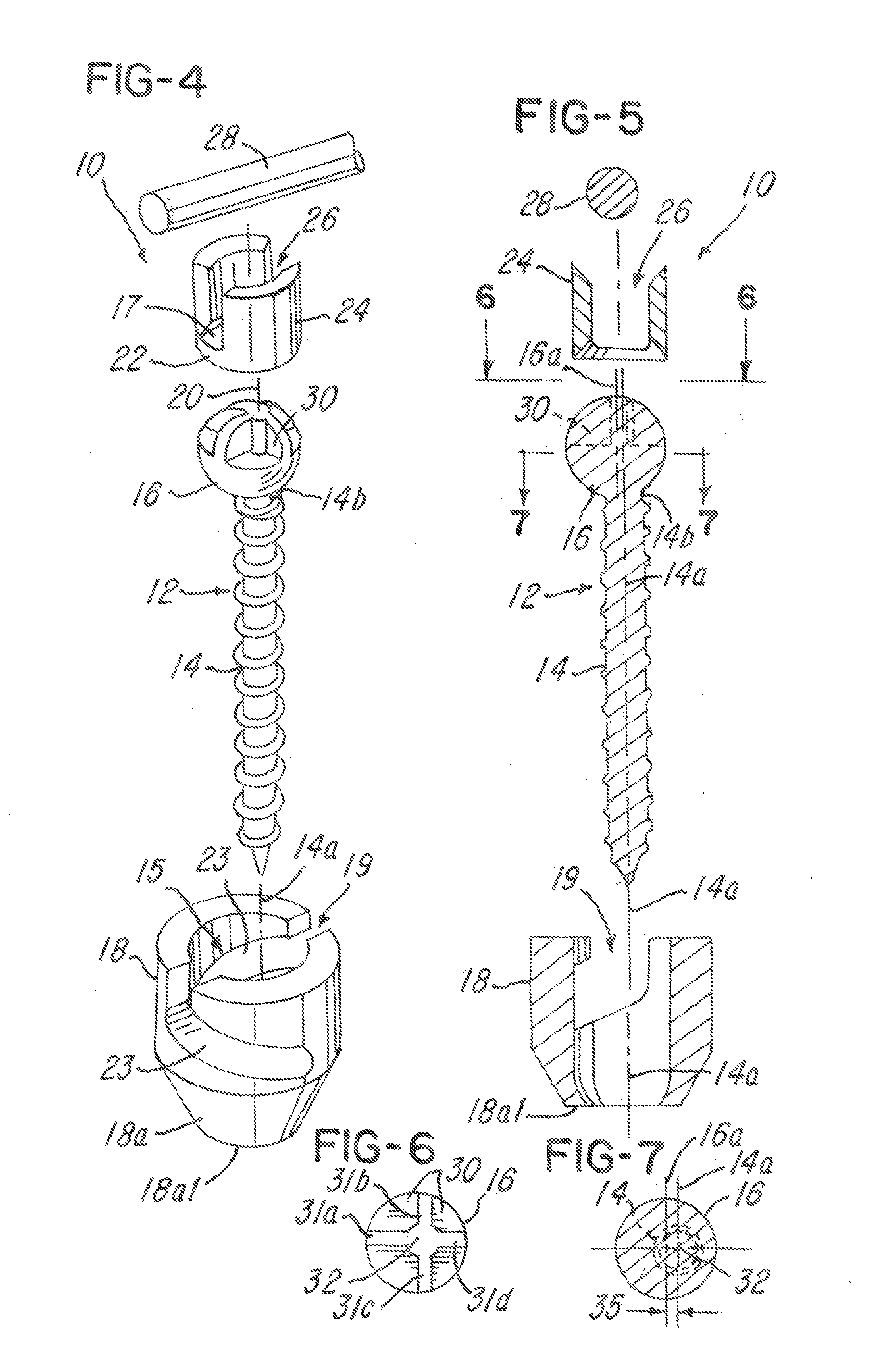
[0061]Referring now to the drawings in detail, wherein identical numerals indicate the same elements throughout the figures, FIGS. 4-35B depict various embodiments of a multi-axial screw and spinal fixation assembly 10. Spinal fixation assembly 10 includes a screw 12 having a threaded portion 14 and a screw head 16 that preferably has a rounded, arcuate, spherical or curved profile. Spinal fixation assembly 10 further includes a retainer 18, which preferably has a generally cylindrical configuration. In these illustrative embodiments, the retainer 18 is capless, but the retainer 18 could be non-capless, such as is illustrated in FIGS. 36 and 37 below. Although not shown, it will be appreciated that retainer 18 includes an aperture or bore 15 therethrough along a centerline axis 20 (FIG. 4). Accordingly, the bore 15 that receives a threaded portion 14 of the screw 12 until screw head 16 thereof is received adjacent a first end 18a of retainer 18. It will be understood that screw head...


PUM


Abstract

A capless multiaxial screw fixation assembly, including: a screw having a threaded portion and a screw head portion positioned at one end thereof; and, a retainer having a first end, a second end opposite the first end, and a bore for receiving the screw threaded portion so that the screw head portion is seated therein. At least one of the screw and the retainer is configured such that the retainer is able to pivot about the screw head portion in a non-symmetrical manner.

Description

BACKGROUND OF THE INVENTION[0001]1. Field of the Invention[0002]The present invention relates generally to a screw having an offset head and to a multiaxial or polyaxial screw for use with a bone fixation system and, in particular, to a multiaxial or polyaxial screw which permits a greater range of pivotability in at least one direction.[0003]2. Description of the Related Art[0004]As is generally known in the art, spinal abnormalities may be correctable using a pair of posterior spinal fixation rods attached to the vertebrae using pedicle screws and the like. In order to provide increased stability and rigidity, especially to resist twisting or the like, the pair of elongated rods often include cross connecting devices. The cross connecting devices typically traverse the spinal column and couple to each of the elongated rods. In other words, the cross connecting devices are perpendicular or substantially perpendicular to the spinal column.[0005]In addition, bone screws with a polyax...

Claims


Application Information

Patent Timeline
IPC IPC(8): A61B17/70A61B17/58A61B17/56
CPCA61B17/7032A61B17/7037A61B17/70A61B17/861A61B17/7082A61B17/7038
Inventor KIRSCHMAN, DAVID LOUIS
Owner X SPINE SYST
Why Eureka
Try Eureka