Ball bearing manufacturing facility and super finish machining apparatus

a manufacturing facility and machining technology, applied in the direction of superfinishing machines, manufacturing tools, other manufacturing equipment/tools, etc., can solve the problems of unstable machining accuracy of the outer ring raceway b>4/b> and the inner ring raceway b>5/b>, and the texture of the workpiece remains unfinished, so as to increase the defect-free off-line parts percentage, improve the effect of effect of

Inactive Publication Date: 2009-07-02
NSK LTD
View PDF0 Cites 7 Cited by
  • Summary
  • Abstract
  • Description
  • Claims
  • Application Information

AI Technical Summary

Benefits of technology

[0038]According to the ball bearing manufacturing facility of the invention which utilizes the super finish machining apparatuses that are configured as described above, since the shift amount for the diameter machining target value for the outer ring raceway or the inner ring raceway is imparted to not only the grinding apparatus but also the super finish machining apparatus, the dimension accuracy and configuration accuracy of the outer ring raceway and the inner ring raceway that are obtained can be increased, thereby making it possible to realize an increase in the defect-free oft-line parts in the assembling process.
[0039]Note that a ball bearing manufacturing method is described in JP-A-51-93480 which includes the steps of determining a dimension of design for a deviation relative to a reference value of the diameter of an outer ring raceway or an inner ring raceway from a mean value of deviations of diameters of outer rings or inner rings measured after the outer rings or inner rings have been machined relative to the reference value and a mean value of deviations of diameters of balls left waiting relative to a reference value thereof or a deviation of diameters of balls which constitute the majority of balls left waiting and feeding the dimension of design so determined back to a machining apparatus for outer ring raceways or inner ring raceways. In addition, a ball bearing manufacturing system is described in JP-A-2000-94226 in which an inner ring raceway of an outer ring raceway is machined in a grinding apparatus so that a bearing interior gap becomes constant based on a measured value of the outer ring raceway or the inner ring raceway after they have been machined at a gauge unit. Additionally, a super finish machining apparatus is described in Japanese Patent Examined Publication JP-B-3,079,666 which incorporates therein an eccentric shaft rotating drive mechanism which enables the movement of a rocking center axis of a super finishing grinding stone to a radial direction of the rotational axis of an outer ring or an inner ring, which constitutes a workpiece to be machined, for positioning of the rocking center axis of the super finishing grinding stone. However, as with the JP-B-2,767,925 and the JP-B-2,767,926, none of the method, system and apparatus described in the JP-A-51-93480, JP-A-2000-94226 and JP-B-3,079,666 takes it into consideration that the shift amount for the diameter machining target value for the inner ring raceway or the outer ring raceway is given to the super finishing machining apparatus. Due to this, in the case of the method, system and apparatuses described in the JP-B-2,767,925, JP-B-2,767,926, JP-A-51-93480, JP-A-2000-94226 and JP-B-3,079,666, there still remains a room to be improved with respect to the increase in defect-free off-line parts percentage in the assembling process. In contrast to this, in the case of the invention, there is caused no such inconvenience.

Problems solved by technology

In this case, the machining allowance of the outer ring 1 and the inner ring 2 by the super finish machining becomes unstable, leading to a possibility that the dimensional accuracy of the diameters of the outer ring raceway 4 and the inner ring raceway 5 after the super finish machining becomes unstable.
Due to this, the grinding capability of the super finishing grinding stone 46 is changed, and the machining allowance by super finish machining becomes unstable, whereby the diameter machining value of the outer ring raceway 4 obtained by the super finish machining does not change accurately according to a given shift amount, leading to a possibility that the machining accuracy of the outer ring raceway 4 becomes unstable.
Furthermore, depending on machining conditions of the outer ring railway 4, there is caused a possibility that the shape of the arc which represents the cross section of the outer ring raceway 4 is deteriorated or a so-called residual texture state results in which a part of the texture of the workpiece remains unfinished that should have been removed by super finish machining.
In addition, the aforesaid problems occur similarly not only when the super finish machining is applied to the outer ring raceway 4 of the outer ring 1 but also when the super finish machining is applied to the inner ring raceway 5 of the inner ring 2.
However, the operation like this constitutes a heavy burden borne by the operator.

Method used


Image

  • Ball bearing manufacturing facility and super finish machining apparatus
  • Ball bearing manufacturing facility and super finish machining apparatus
  • Ball bearing manufacturing facility and super finish machining apparatus

Examples


embodiment 1

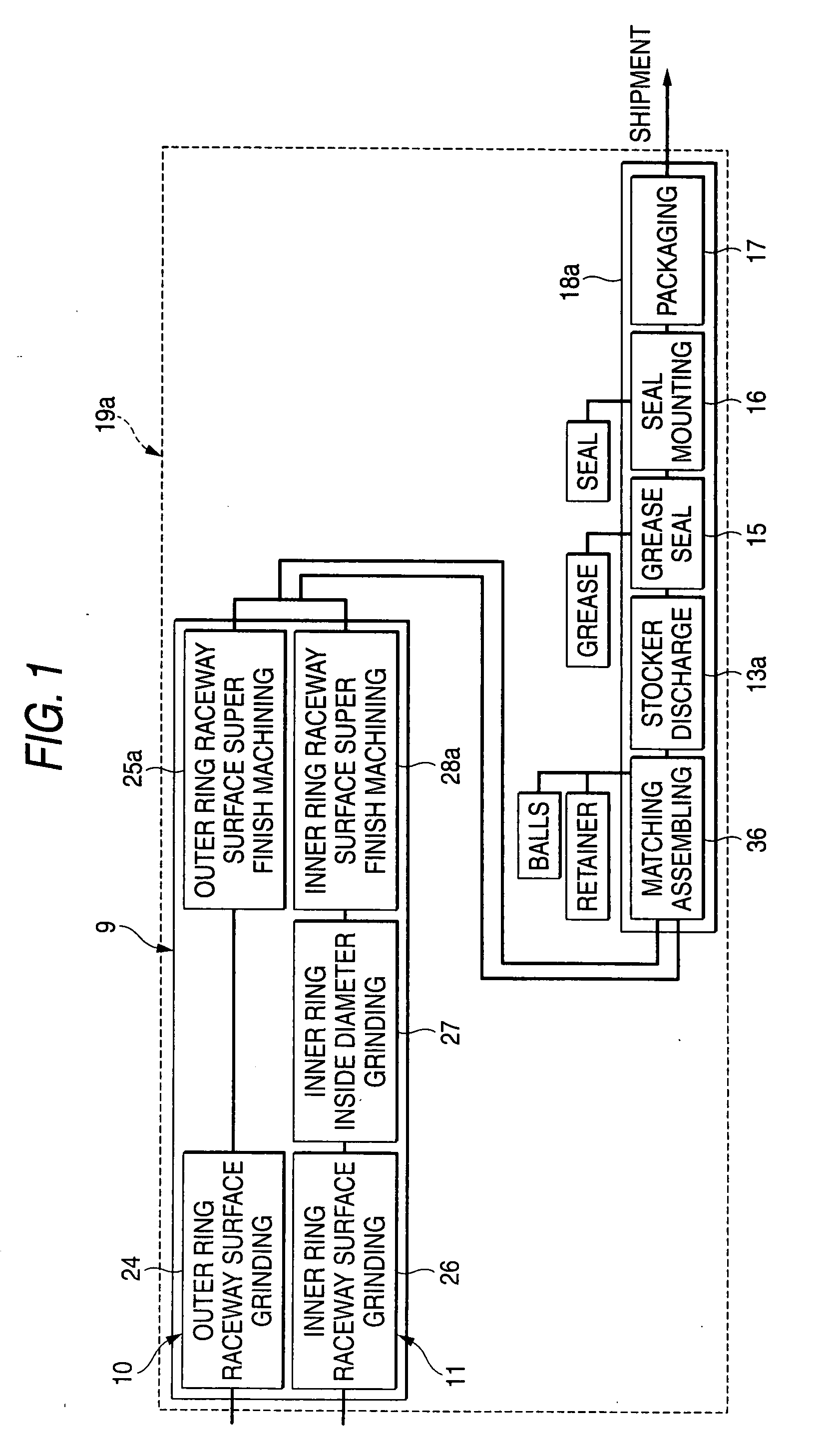
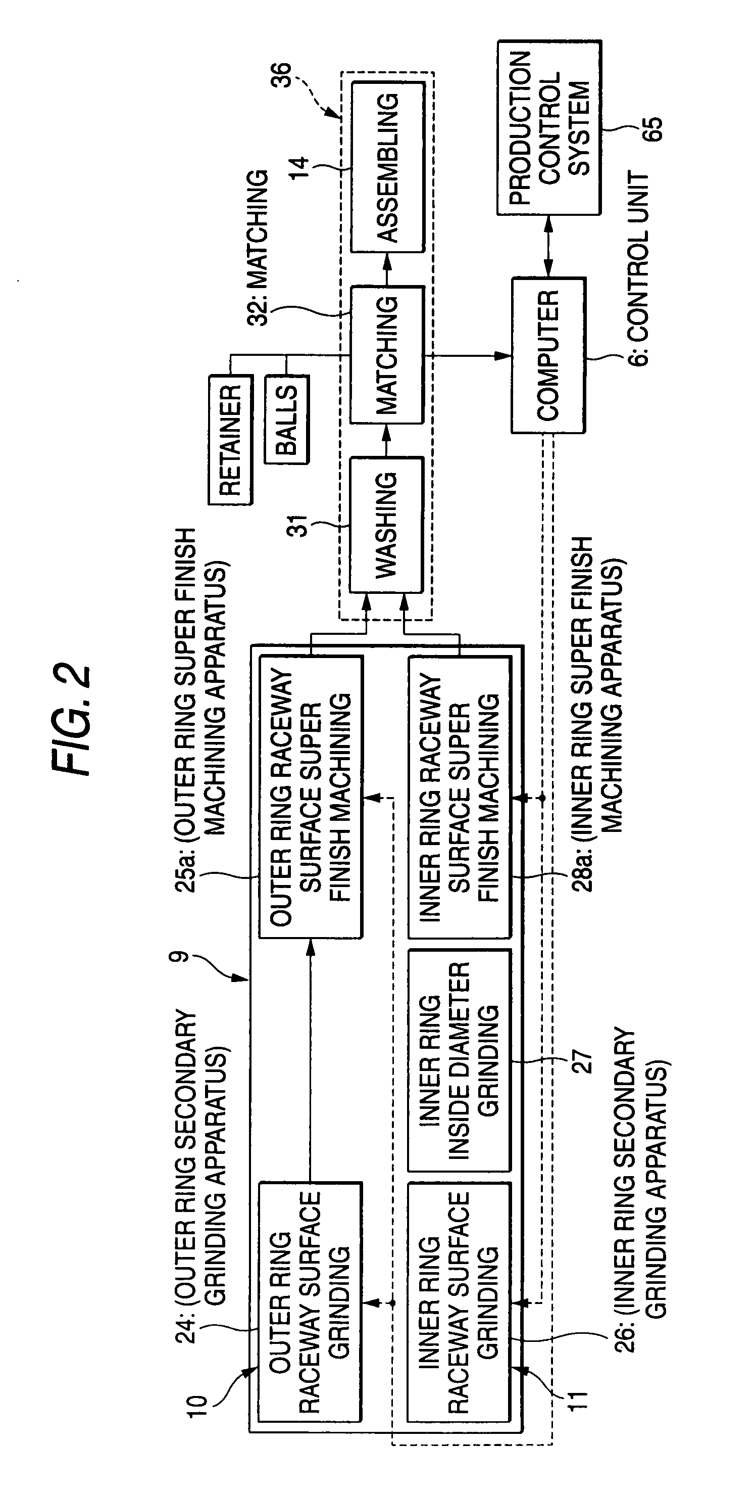
[0066]FIGS. 1 to 4 shown an embodiment of the invention. In the case of a ball bearing manufacturing facility of the invention, with respect to a carrying direction (a flowing direction) (a horizontal direction in FIG. 1) of an outer ring 1, an inner ring 2 (refer to FIG. 6) or an intermediate assembly, which is a workpiece (work), a stocker 13a, which enables the storage and discharge of a plurality of intermediate assemblies, is provided between matching assembling equipment 36 and a grease sealing apparatus 15. In addition, the matching assembling equipment 36 includes, as shown in FIG. 2, a washing apparatus 31 for washing an outer ring 1 and an inner ring 2 which have been ground and machined to be given a super finish, a matching apparatus 32 for selecting an outer ring 1 and an inner ring 2 from those sent from the washing machine 31 and balls 3 (refer to FIG. 6) which have proper dimensions, respectively, for combination and an assembling apparatus 14 for fabricating an inte...


PUM

PropertyMeasurementUnit
diameteraaaaaaaaaa
diametersaaaaaaaaaa
circumferencesaaaaaaaaaa

Abstract

A detection unit of a matching apparatus 32 is connected to a control unit 6 of a computer so that a detection signal indicating measured values of diameters of outer and inner ring raceways can be sent thereinto. An outer ring secondary grinding apparatus 24, an cuter ring super finish machining apparatus 25a, an inner ring secondary grinding apparatus 26 and an inner ring super finish machining apparatus 28a are connected to the control unit 6 so that control signals can be received. The control unit 6 imparts shift amounts to diameter machining target values which are set, respectively, in the grinding apparatus 24, 26 and the super finish machining apparatus 25a, 28a for machining a raceway surface of at least one bearing ring of outer and inner rings, based on measured values of diameters of the outer and inner ring raceways which were measured by the detection unit.

Description

TECHNICAL FIELD[0001]The present invention relates to an improved ball bearing manufacturing facility having bearing ring machining equipment for machining bearing rings for ball bearings and assembling equipment for assembling the bearing rings and balls together, and an improved super finish machining apparatus for use in the manufacturing facility.BACKGROUND ART[0002]A construction such as shown in FIG. 6 is known as a ball bearing. Note that in FIG. 6, a bearing gap is illustrated in an exaggerated fashion as will be described later on. This ball bearing is made up by placing a plurality of balls 3, 3 between an outer ring 1 and an inner ring 2 which are disposed concentrically with each other. Among these constituent components, an outer ring raceway 4 and an inner ring raceway 5 are formed on inner circumferential surface of the outer ring 1 and an outer circumferential surface of the inner ring 2 in such a manner as to extend along the full circumferences of the outer ring 1 ...

Claims


Application Information

Patent Timeline
Patent Type & Authority Applications(United States)
IPC IPC(8): B23P23/04
CPCB24B19/06B24B35/00Y10T29/51F16C33/64B24B49/00F16C19/06B24B49/06
Inventor SENSUI, NATSUKIJOHNISHI, SHUJIIRIE, YOSUKE
Owner NSK LTD
Why Eureka
Try Eureka