Method and device for the production of a stamping with almost smooth cutting and enlarged functional surface

a technology of functional surface and cutting edge, which is applied in the direction of stripping device, ejection device, presses, etc., can solve the problems of reducing the functionality of parts, reducing the cutting surface, and limited parts functionality, so as to reduce the edge rollover at the part, reduce the edge rollover, and reduce the quality of the blank. the effect of reducing the risk of developing tears

Active Publication Date: 2009-07-02
FEINTOOL INT HLDG
View PDF5 Cites 15 Cited by
  • Summary
  • Abstract
  • Description
  • Claims
  • Application Information

AI Technical Summary

Benefits of technology

[0015]It is of special advantage that the parameters for controlling the state of stress in the cutting zone, for example the volume of material to be additionally pressed in depending on the type of material, shape and geometry of the workpiece can be determined by a virtual forming simulation according to the results of which are then designed the tool elements for pressing additional material in the direction of the cutting zone.
[0016]It is of significant importance that with the method according to this invention it is possible to press additional material into the cutting zone in transversal direction, thereby significantly reducing the edge rollover at the part. By maintaining the state of stress in the cutting zone in the area where the pressure is applied, it is guaranteed that the cutting surfaces are smooth and free of tears. Further, the functional surfaces, because of the reduced edge rollover, are almost free of rollover.
[0017]Thus, the method according to this invention in high quality covers fine blanking in a wide range of dimensions, for example parts up to great thicknesses and complex part geometries, as for instance toothings of driving gears. Furthermore, with the method according to this invention it is also possible to fine blank lower steel qualities without running the risk of developing tears at the cutting surfaces.
[0018]The device according to this invention has a simple and sturdy structure.

Problems solved by technology

It is known that fine blanking at projecting contours of parts, for example toothings or corners, often leads to tears at the cutting surfaces.
Thus, the rollover depends on material thickness and quality, so that the possibility to control it is limited and often brings about a limited functionality of parts, for example due to a lack of sharp edges of the corners at toothed parts or the caused change in the functional length of the parts.
The stamping rollover thus reduces the functionality of parts and urges the manufacturer to use a thicker raw material.
The known solutions according to CH 665 367 A5 and DE 197 38 636 A1 do not reduce the edge rollover, but largely rework the parts, so that on the one hand, significant costs for additional machining operations and tools are required and, on the other hand, a respective loss of material due to the necessity of using thicker materials occurs.
Also with this known solution the rollover lastly is not avoided and material volume is shifted along the cutting line, which is accompanied by an increased risk of developing tears.
Also with this known solution, the rollover lastly is not avoided and material volume is shifted along the cutting line, which is accompanied by an increased risk of developing tears.

Method used


Image

  • Method and device for the production of a stamping with almost smooth cutting and enlarged functional surface
  • Method and device for the production of a stamping with almost smooth cutting and enlarged functional surface
  • Method and device for the production of a stamping with almost smooth cutting and enlarged functional surface

Examples


embodiment 1

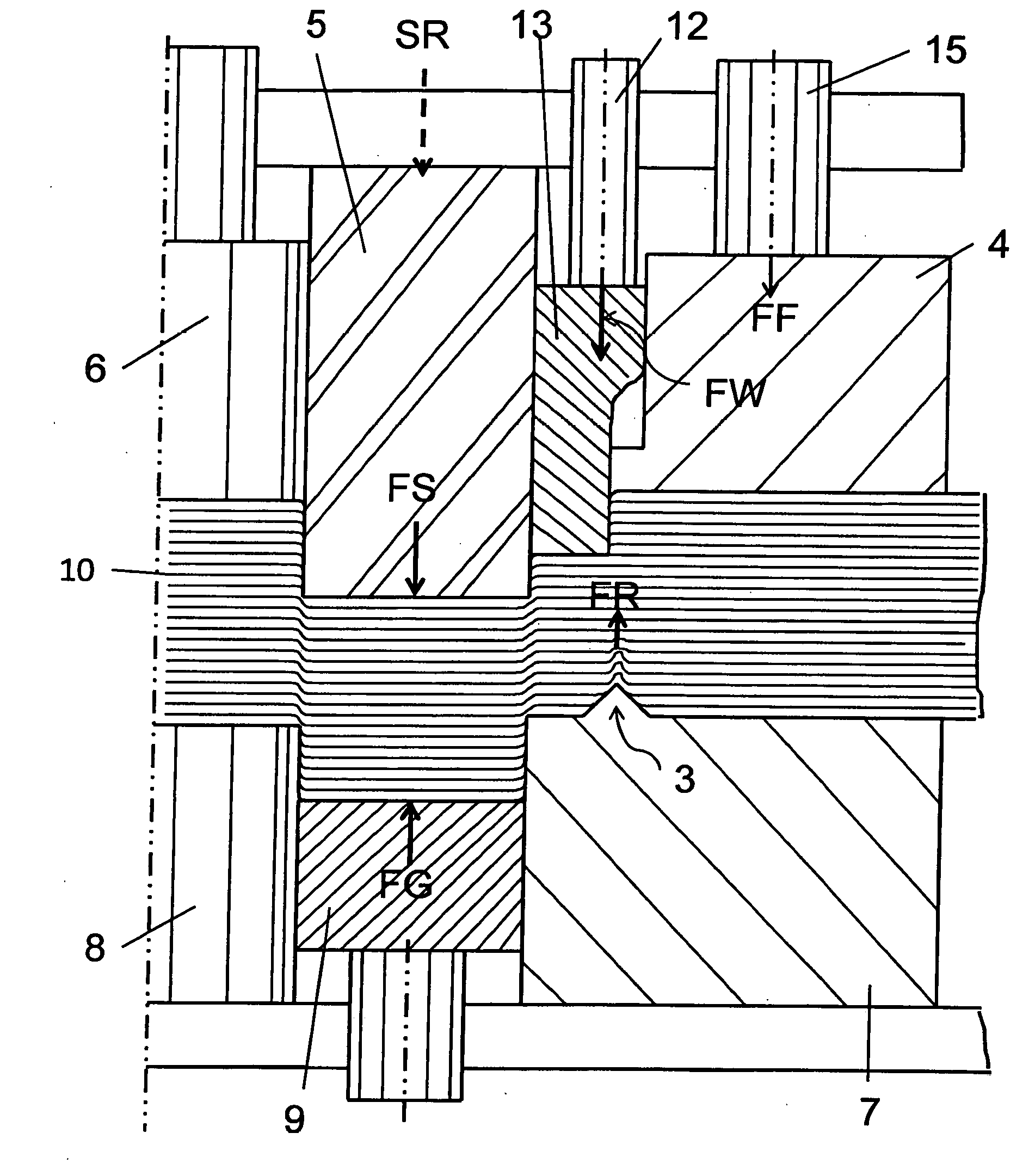
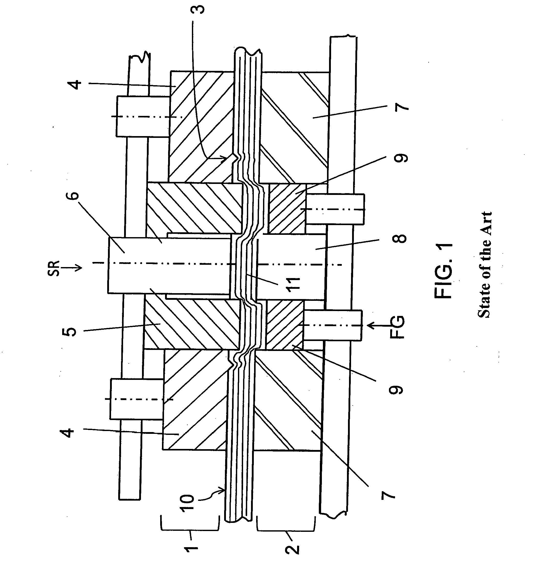
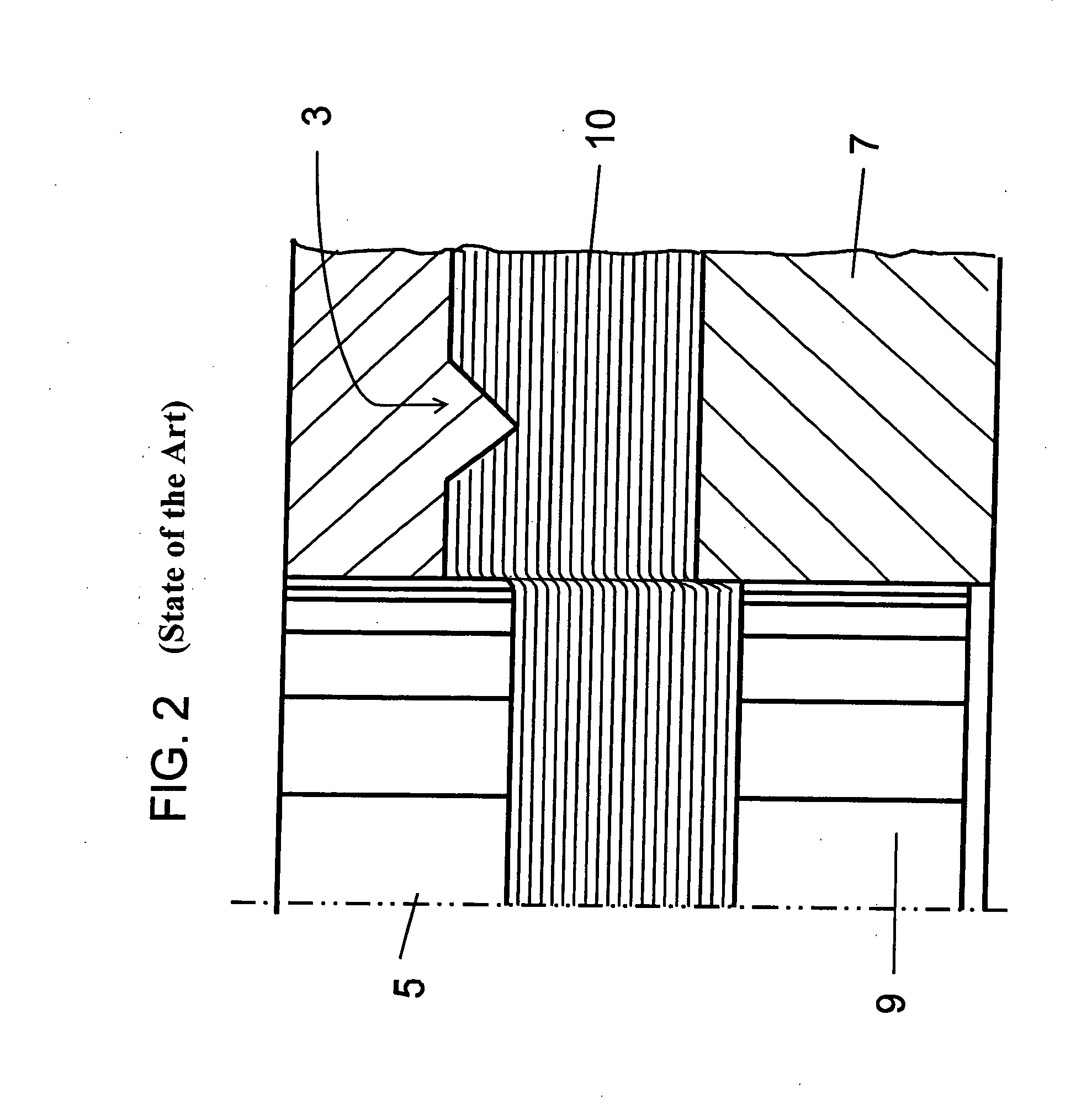
[0031]The device according to this invention in embodiment 1 substantially corresponds to the structure of the device described according to FIG. 1, but with the difference, that a V-shaped projection 3 is arranged on cutting die 7. Instead of the previously allocated to pressure pad 4, V-shaped projection is provided an active tool element 13, which can be applied and operated via a hydraulic stud 12, that acts with the respective force FW in the direction of the cutting line SL on the flat strip 10 (see, for example, FIG. 3). The tool element 13 on one side is supported by shearing punch 5 and on the other side by a recess formed into pressure pad 4, and is vertically moveable with regard to the flat strip. In FIG. 3 the flat strip 10 does not have a free punch and the active tool element 13 is not yet engaged. The flat strip 10 in clamped state lies between upper and lower parts of the device according to this invention. The lower V-shaped projection 3 has penetrated the flat str...

embodiment 2

[0038]FIG. 6 shows a further aspect of the device according to this invention, the basic structure of which corresponds with the structure of the device described in FIG. 3.

[0039]In addition to the V-shaped projection 3 on the cutting die 7, a supporting platform 16 coming to lie in the free punch 17 is provided. The supporting platform 16 prevents the material from flowing into breadth. All other processes correspond with those of embodiment 1.


PUM

PropertyMeasurementUnit
thicknessaaaaaaaaaa
compressive stressaaaaaaaaaa
thicknessaaaaaaaaaa

Abstract

A method and device for production of stampings with an almost smooth cutting and enlarged functional surface, especially fine blanking and/or forming a workpiece out of a flat strip, wherein flat strip is clamped between an upper part consisting of a shearing punch, a pressure pad, a V-shaped projection and an ejector arranged on the pressure pad, and a lower part consisting of cutting die, ejector and an inner form stamp. By adjusting the state of stress in the cutting zone to a position oriented compressive stress by movement slightly retarded with regard to movement of the shearing punch additionally pressing in material in a direction almost perpendicular to the cutting direction by a tool element acting with controlled force depending on the part geometry and thickness of the workpiece parallel to the cutting line between shearing punch and cutting die, tears at cutting and reduced rollover are achieved.

Description

BACKGROUND OF THE INVENTION[0001]The invention relates to a method for the production of stampings with an almost smooth cutting and enlarged functional surface, especially fine blanking and / or forming a workpiece out of a flat strip, wherein the flat strip at closing is clamped between an upper part consisting of a shearing punch, a pressure pad for the shearing punch, a V-shaped projection arranged on the pressure pad, and an ejector and a lower part consisting of a cutting die, an ejector and an inner form stamp, and in the cutting zone a cut is enforced by shearing at high compressive stress, wherein the V-shaped projection has been pressed into the flat strip beforehand and a compressive stress acts on the flat strip to be cut.[0002]The invention further relates to a device for the production of stampings with an almost smooth and enlarged functional surface, especially fine blanking and / or forming a workpiece out of a flat strip, with a tool having two parts comprising at leas...

Claims


Application Information

Patent Timeline
Patent Type & Authority Applications(United States)
IPC IPC(8): B21D28/02B21D31/00B21D45/02
CPCB21D28/16B30B15/00B30B15/02
Inventor SCHLATTER, ULRICHHORA, PAVEL
Owner FEINTOOL INT HLDG
Why Eureka
Try Eureka