Vibration-Type Inertia Force Sensor And Electronic Apparatus Using The Same

a technology of inertia force sensor and electronic apparatus, which is applied in the direction of turn-sensitive devices, instruments, television systems, etc., can solve the problems of preventing power consumption and achieve the effect of reducing power consumption

Inactive Publication Date: 2009-07-02
PANASONIC CORP
View PDF13 Cites 9 Cited by
  • Summary
  • Abstract
  • Description
  • Claims
  • Application Information

AI Technical Summary

Benefits of technology

[0007]The present invention has been made in view of the above disadvantage. The present invention provides a vibration-type inertia force sensor that can reduce power consumption when being installed in an electronic device such as a digital camera and an electronic device using the same.

Problems solved by technology

This has caused a problem where the suppression of power consumption is hindered.

Method used


Image

  • Vibration-Type Inertia Force Sensor And Electronic Apparatus Using The Same
  • Vibration-Type Inertia Force Sensor And Electronic Apparatus Using The Same
  • Vibration-Type Inertia Force Sensor And Electronic Apparatus Using The Same

Examples


first embodiment

[0076]First, a vibration-type inertia force sensor in the first embodiment of the present invention will be described. In the first embodiment, an angular speed sensor will be described as the vibration-type inertia force sensor.

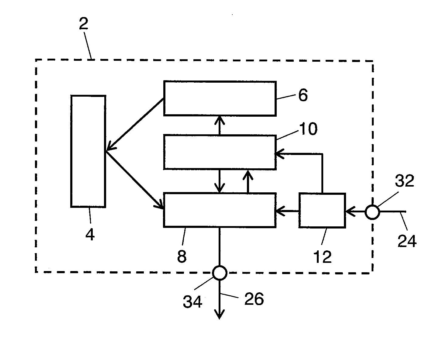
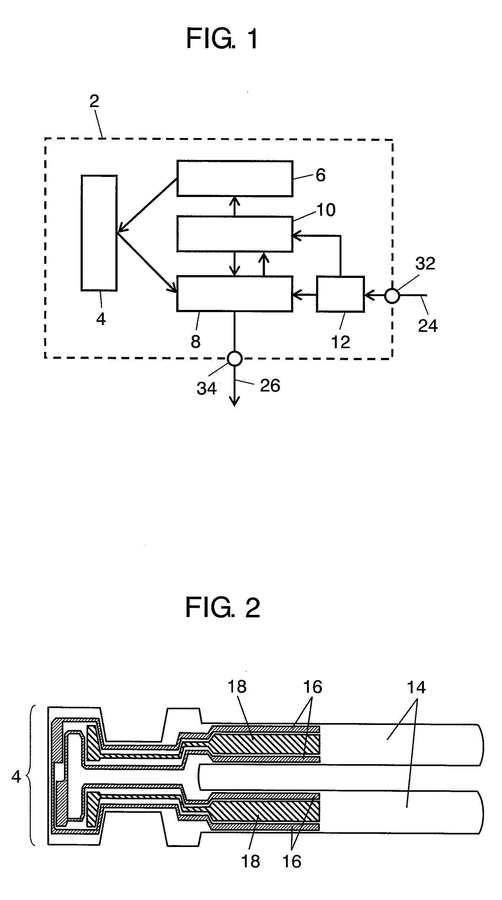
[0077]FIG. 1 is a block diagram illustrating the structure of angular speed sensor 2 in the first embodiment of the present invention. FIG. 2 is a top view illustrating the structure of oscillator 4 of angular speed sensor 2.

[0078]First, angular speed sensor 2 in FIG. 1 includes: oscillator 4 having a structure which will be described later; driving circuit 6 that is a driving section for oscillating oscillator 4; sensing circuit 8 that is a sensing section for sensing the strain caused in oscillator 4 due to the Coriolis force (inertia force); and power supply circuit 10 that is a power supply section for supplying power to driving circuit 6 and sensing circuit 8 in a normal state.

[0079]Sensing circuit 8 also has a function to determine, when oscillator 4 d...

second embodiment

[0094]Next, an electronic device of the second embodiment of the present invention will be described in detail. In the second embodiment, digital camera 40 will be described as an example of the electronic device.

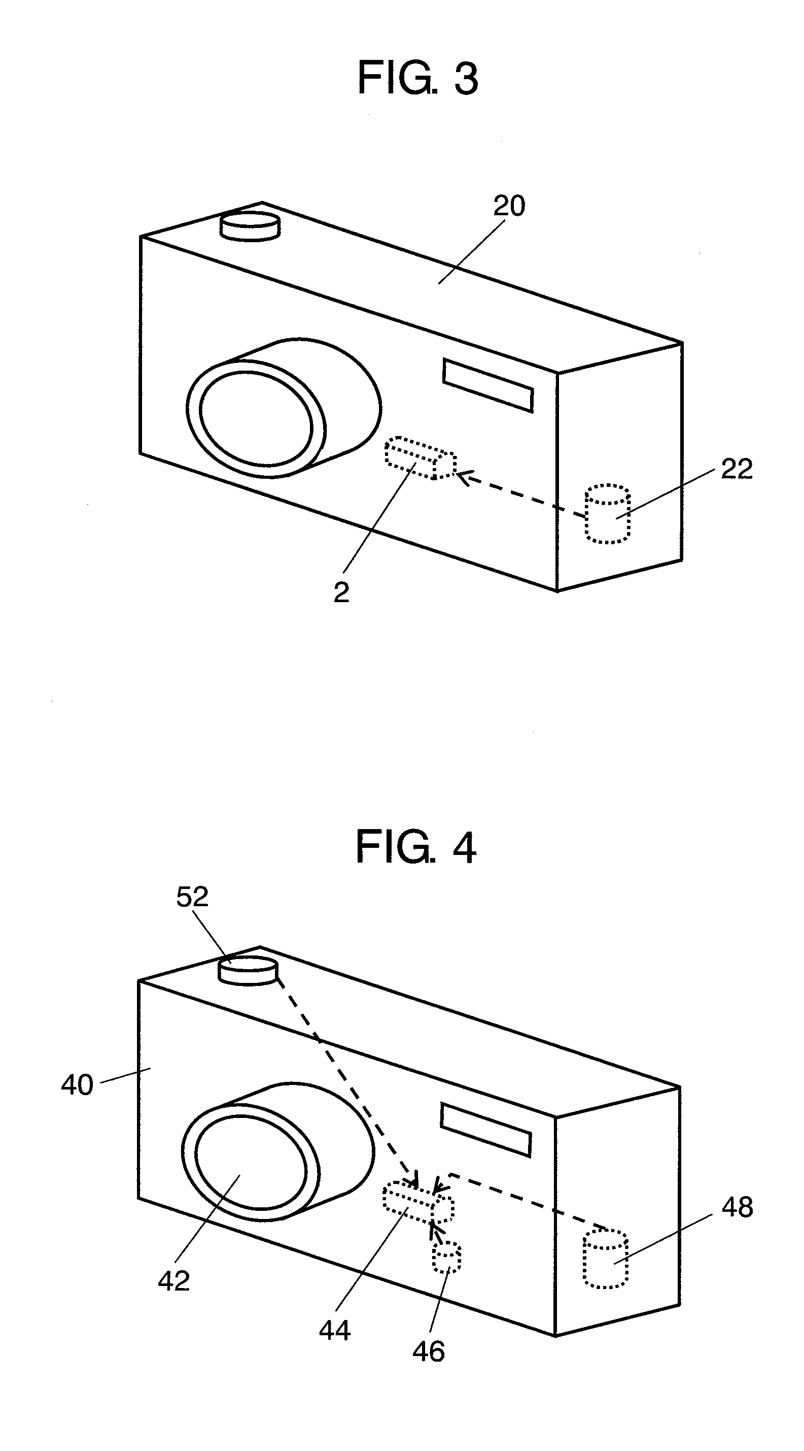
[0095]FIG. 4 is a schematic view illustrating digital camera 40 in the second embodiment of the present invention. Digital camera 40 has a characteristic structure in which a device body has an image stabilizer function to optical system 42 having a lens and CCD. As a part of a system configuration realizing this image stabilizer function, vibration-type inertia force sensor 44 is attached to digital camera 40. Based on a detection signal from inertia force sensor 44, optical system 42 can be controlled to provide image stabilization in digital camera 40.

[0096]Digital camera 40 is driven by battery 48 for which the suppression of the power consumption is important. Thus, the sleep function is used by which the minimum power supply to the main functions is set when digital c...

third embodiment

[0109]Next, an electronic device in the third embodiment of the present invention will be described in detail with reference to the drawings. The third embodiment will be also described by way of a digital camera as an example of an electronic device.

[0110]FIG. 7 is a schematic view illustrating digital camera 70 in the third embodiment of the present invention. FIG. 8 is a block diagram illustrating the structure of an inertia force sensor used in the electronic device.

[0111]Digital camera 70 has an image stabilizer function as a characteristic structure to optical system 42 having a lens and a CCD provided in the device body. As a part of a system configuration realizing the image stabilizer function, vibration-type inertia force sensor 44 as an angular speed sensor is attached to digital camera 70. Based on a detection signal from inertia force sensor 44, an unstable image due to the jiggling of hands holding the digital camera can be prevented.

[0112]Inertia force sensor 44 used ...


PUM


Abstract

A vibration-type inertia force sensor includes: an oscillator; a driving section for oscillating the oscillator; a sensing section for sensing a strain caused in the oscillator due to an inertia force; and a power supply section for supplying power to the driving section and the sensing section in a normal state and for supplying power to one of the driving section and the sensing section and not supplying power to the other of the driving section and the sensing section in a power-saving state.

Description

TECHNICAL FIELD[0001]The present invention relates to a vibration-type inertia force sensor used in various electronic devices and an electronic device using the same.BACKGROUND ART[0002]First, a conventional vibration type inertia force sensor will be described. Vibration-type inertia force sensors include an angular speed sensor for example. This angular speed sensor includes: an oscillator; a driving circuit for oscillating this oscillator; a sensing circuit for sensing strain caused by Coriolis force (inertia force); and a power supply circuit for supplying power to the driving circuit and the sensing circuit.[0003]The oscillators of the angular speed sensor include the tuning fork-like shape one, the H-like shape one, the T-like shape one or others having various shapes. The angular speed sensor calculates an angular speed by oscillating this oscillator to electrically detect the strain of the oscillator due to the generation of the Coriolis force (see Japanese Patent Unexamine...

Claims


Application Information

Patent Timeline
Patent Type & Authority Applications(United States)
IPC IPC(8): G01C19/56
CPCG01C19/5607H04N1/00127H04N1/00323H04N5/2251H04N2201/0084H04N5/23248H04N5/23258H04N5/23264H04N2101/00H04N5/23241H04N23/50H04N23/651H04N23/682H04N23/68H04N23/6812
Inventor UEMURA, TAKESHI
Owner PANASONIC CORP
Why Eureka
Try Eureka