
Air velocity indicator and control device

a control device and air flow velocity technology, applied in the field of pneumatic particulate matter distribution systems, can solve the problems of wasting energy in the process, compromising the integrity and consistency of the seeding volume as a function of time and/or seeding distribution pattern upon the ground, and affecting the quality of the air flow, so as to electronic complexity, reduce the number of parts, reduce the effect of energy waste, and reduce the number of electronic components

Inactive Publication Date: 2009-07-02
CNH IND AMERICA LLC
View PDF12 Cites 26 Cited by
  • Summary
  • Abstract
  • Description
  • Claims
  • Application Information

AI Technical Summary

Benefits of technology

[0011]There is a need for an air seeder that provides monitoring and regulation of airflow velocities within a pneumatic distribution system, to mitigate airflow velocities differentials between individual air lines. There is also a need for an air seeder that reduces the number of parts and electronic complexity of pneumatic distribution system monitoring devices. Furthermore, there is a need for air seeders with pneumatic distribution systems that can be regulated and adjusted manually and / or automatically on a per individual air line basis, whereby inconsistent seed coverage, underplanting, overplanting, and energy wasting can be managed and minimized.
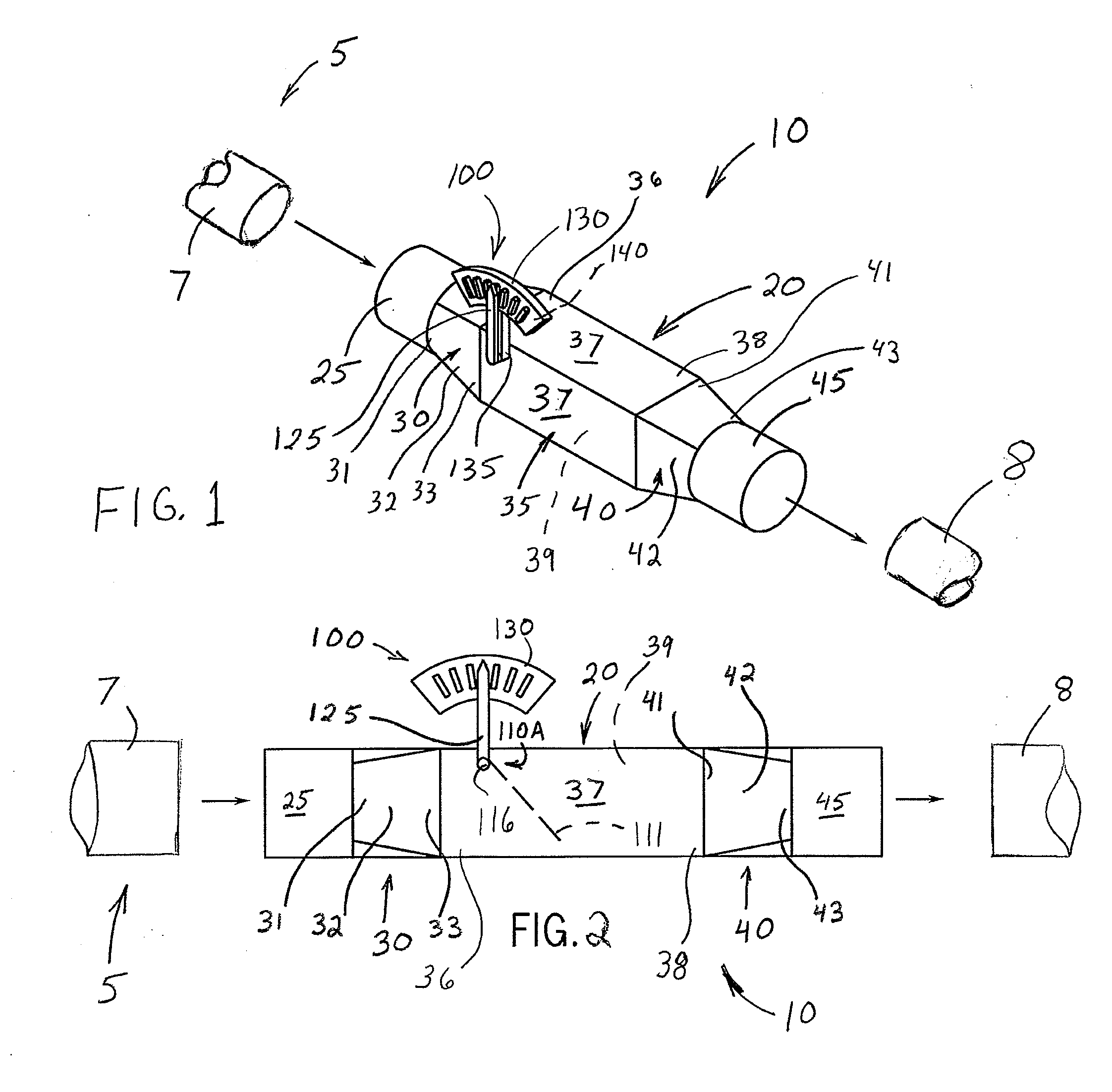
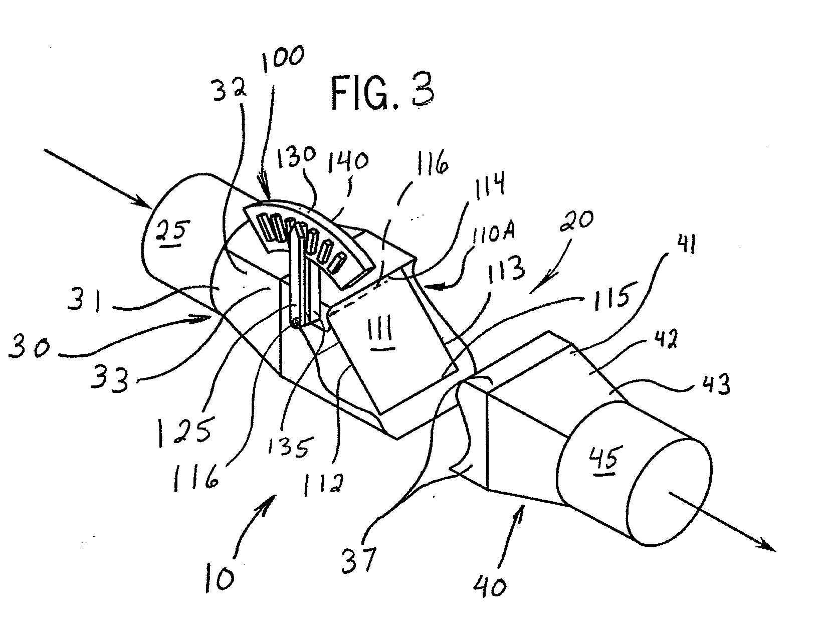
[0012]The present invention provides an airflow velocity indicator and control mechanism or device which meets the desires and needs described above, while being used, e.g., in combination with an air seeder. In a first embodiment of the present invention, the air velocity indicator and control device includes an inlet and an outlet, with a tubular housing extending therebetween. A deflectable plate is provided in the housing and configured to actuate in response to encountering the airflow entrained with agricultural product. A magnitude of deflection of the deflectable plate is displayed through an indicator assembly, such that the indicator assembly shows a value for the airflow velocity through the device. This enables a user to identify velocity variances and differentials between various components of the air seeder and make corrective adjustments as desired.

Problems solved by technology

In light of precision-type agricultural practices and desire to improve efficiency, known air seeders exhibit certain limitations.
For example, at times during use, various components of the pneumatic distribution system can encounter flow resistances and corresponding operating pressures and flow velocities that are outside of a desired or optimal range.
As a result, the integrity and consistency of the seeding volume as a function of time and / or seed distribution pattern upon the ground, field, seedbed, or furrow can be compromised.
Correspondingly, overseeding, underseeding, or inconsistent seeding distribution patterns can result.
This excessive airflow velocity requires higher static air line pressure(s) to transmit, which in turn requires more power input to achieve, potentially wasting energy in the process.
Furthermore, the excessive airflow velocity causes excessive abrasive wear to the inner surfaces of the air line.
Namely, the airflow entrained product collides with such inner surfaces at a corresponding greater velocity, thus with more force and greater frequency, thereby causing more abrasive damage.
Conversely, a minimum airflow velocity must be maintained to suitably entrain and transport the product through the air seeder, whereby airflow velocities falling below the minimum can result in plugging, clogging, or accumulation of product within the pneumatic delivery system.
While such systems have been adequate, they require sophisticated electronics and controls, and are relatively expensive to produce and maintain.

Method used


Image

  • Air velocity indicator and control device
  • Air velocity indicator and control device
  • Air velocity indicator and control device

Examples


Embodiment Construction

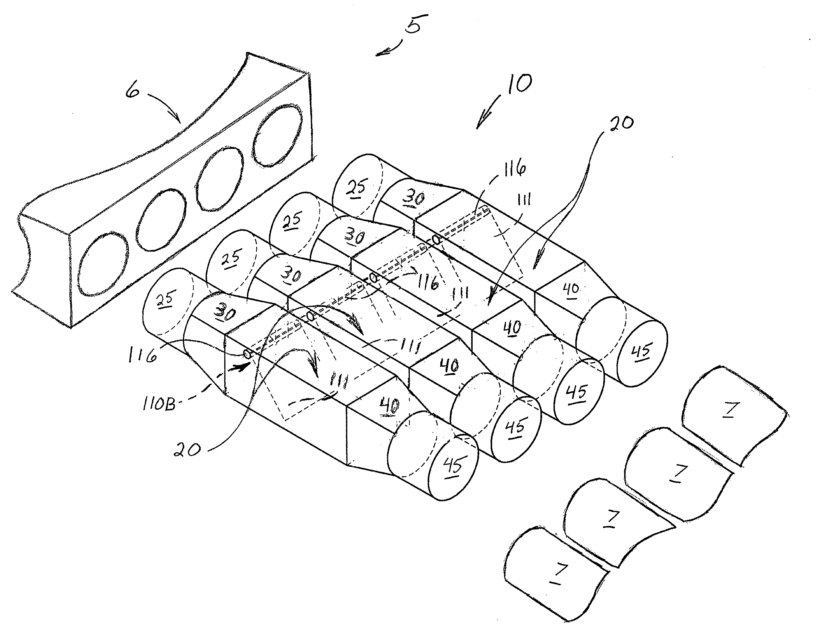
[0021]FIG. 1 shows a preferred embodiment of an air velocity indicator and control device 10 employed on a pneumatic distribution system 5 of an air seeder (not shown). Although no specific air seeder is illustrated, it is well understood that air velocity indicator and control device 10 can be incorporated into any of a variety of suitable air seeders and air seeder components, e.g. air carts and tillage implements, such as various ones manufactured by CNH America LLC. Suitable air carts include Case IH models ADX2230, ADX3380, ADX3430 air carts, and others. Suitable tillage implements include Case IH models ATX400 and ATX700 air hoe drills.

[0022]Notwithstanding, air velocity indicator and control device 10 can be used with yet other known and available air seeders. Known, readily available, air seeders typically include an air cart and a tilling implement, towed in tandem behind a tractor, for pneumatically distributing seed or other particulates or granular product such as fertil...


PUM


Abstract

An air velocity indicator and control device is provided for use with pneumatic distribution systems used in air seeders that pneumatically discharge agricultural product to the ground, seedbed, or furrow. The air velocity indicator and control device includes a tubular housing, extending between an inlet and an outlet, and pivotally housing a deflectable plate that actuates in response to encountering an airflow entrained with agricultural product. A magnitude of deflection of the deflectable plate, corresponding to airflow velocity, can be displayed through an indicator assembly. This enables a user to identify velocity variances and differentials within the air seeder and make corrective adjustments. In some implementations, multiple air velocity indicator and control devices are ganged together with deflectable plates that pivot in unison with each other. The relative angle of fixation of the deflectable plates, upon the pivot pin, can be adjusted to permit airflow tuning as needed.

Description

FIELD OF THE INVENTION[0001]The invention relates generally to pneumatic particulate matter distribution systems for agricultural applications, and in particular, to a device and corresponding method for monitoring and regulating airflow rate differentials between multiple air lines in such pneumatic particulate matter distribution systems.BACKGROUND OF THE INVENTION[0002]Modern pneumatic particulate distribution systems, commonly referred to as air seeders, are used to distribute seed, fertilizer, or other particulate matter during various agricultural practices. Air seeders typically include an air cart and a tilling implement which are towed in tandem behind a tractor.[0003]The air cart includes a frame riding upon wheels and tires, and one or more frame-mounted product tanks for holding granular product, such as seed, fertilizer, herbicide and / or other product. The product tanks are each connected to a product metering device which feeds the product into a pneumatic distribution...

Claims


Application Information

Patent Timeline
IPC IPC(8): A01C7/20
CPCA01C7/102A01C7/082Y10S111/903Y02P60/00
Inventor MEMORY, RUSSELL J.NEUDORF, BLAKE R.
Owner CNH IND AMERICA LLC
Learn More