Injection cylinder in injection apparatus for molding metal material

Inactive Publication Date: 2009-07-02
NISSEI PLASTIC IND CO LTD
View PDF3 Cites 0 Cited by
  • Summary
  • Abstract
  • Description
  • Claims
  • Application Information

AI Technical Summary

Benefits of technology

[0021]The injection cylinder according to the present invention also covers the following aspect: the flange around the rear end of the nozzle member has such a thickness that the front end face of the flange protrudes from the front end face of the opening of the cylinder body when the flange is fitted into the opening of the cylinder body; and the protrusion of the front end face of the flange creates a tightening gap between the front end face of the opening and the rear end face of the coupling ring.
[0022]According to the present invention, the flange of the cylinder liner and the flange of the nozzle member are fitted to the opening in the front end of the cylinder body so that the front end of the cylinder liner and the rear end of the nozzle member are in contact with each other. The nozzle member is also pressed against the cylinder body by means of the coupling ring and the bolt. The flange of the cylinder liner can thus be pressed into contact with a seating surface of the first fitting part, whereby the nozzle member is coupled to and the cylinder liner is fixed to the cylinder body. Besides, the fastening force of the bolt to the coupling ring concentrates upon the flange of the cylinder liner through the nozzle member. Consequently, the fixing and the coupling inside the opening of the cylinder body can be achieved tightly without a gap even in the absence of seal members, making it possible to prevent the leakage of the molten material from between the cylinder body and the nozzle member even with the tight fit.
[0023]The nozzle member can be coupled to and the cylinder liner can be fixed to the cylinder body simply by fastening the coupling ring to the cylinder body with the bolt. This eliminates the need for bolts that fix the cylinder liner to the seating surface of the fitting part in the opening of the cylinder body, and for bolt holes in the flange of the cylinder liner. This also facilitates replacing the cyl

Problems solved by technology

With a shrink fit, the cylinder liner is difficult to pull out.
A gap can thus result from insufficient contact if the inside diameter of the cylinder and the outside diameter of the cylinder liner have too large a tolerance.
Meanwhile, too small a tolerance makes the insertion of the cylinder liner into the cylinder body before the thermal expansion operation so tight that the two members suffer unnecessary stress from thermal expansion.
The application of injection pressure upon each molding also contributes to a drop in durabilit

Method used


Image

  • Injection cylinder in injection apparatus for molding metal material
  • Injection cylinder in injection apparatus for molding metal material
  • Injection cylinder in injection apparatus for molding metal material

Examples


Embodiment Construction

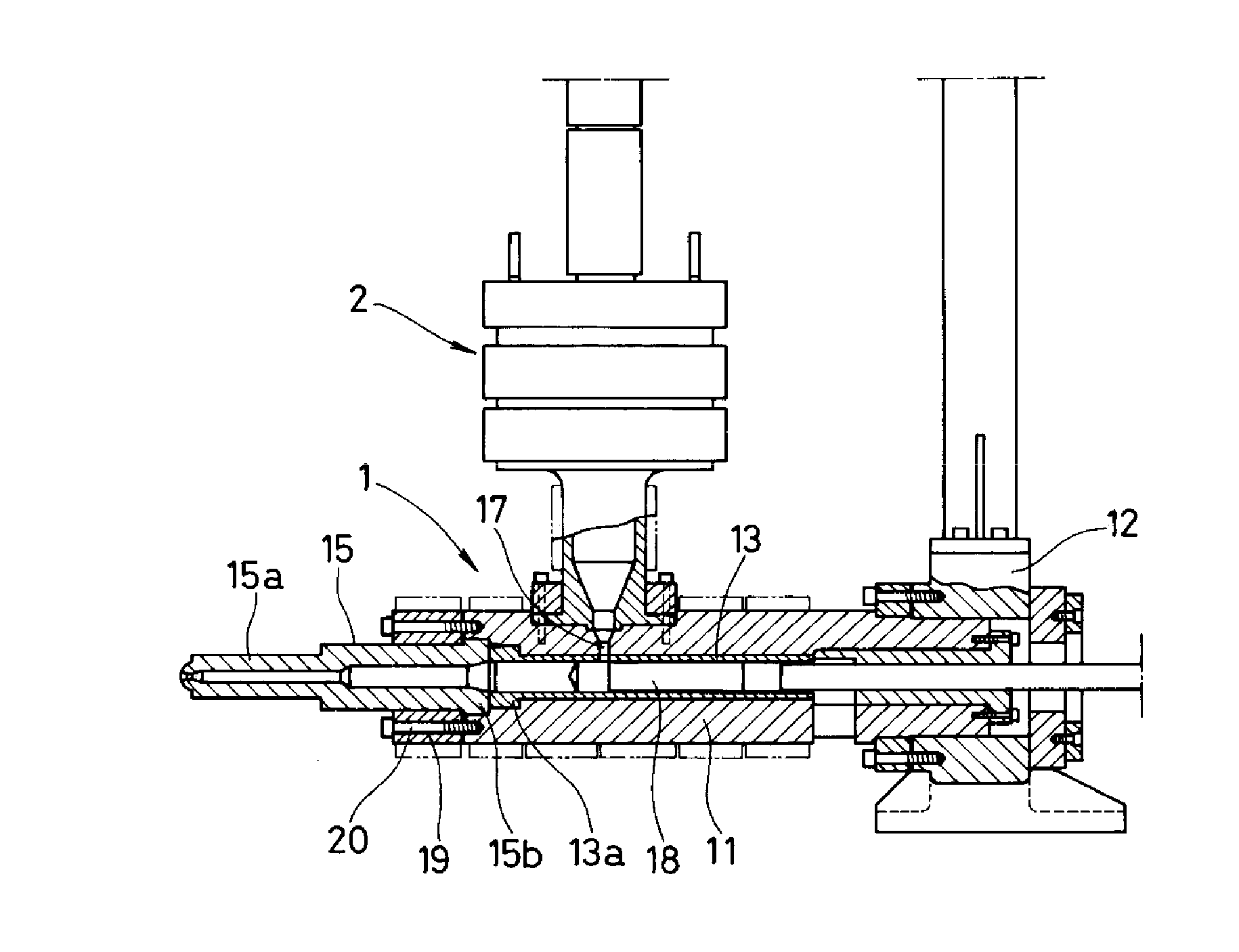
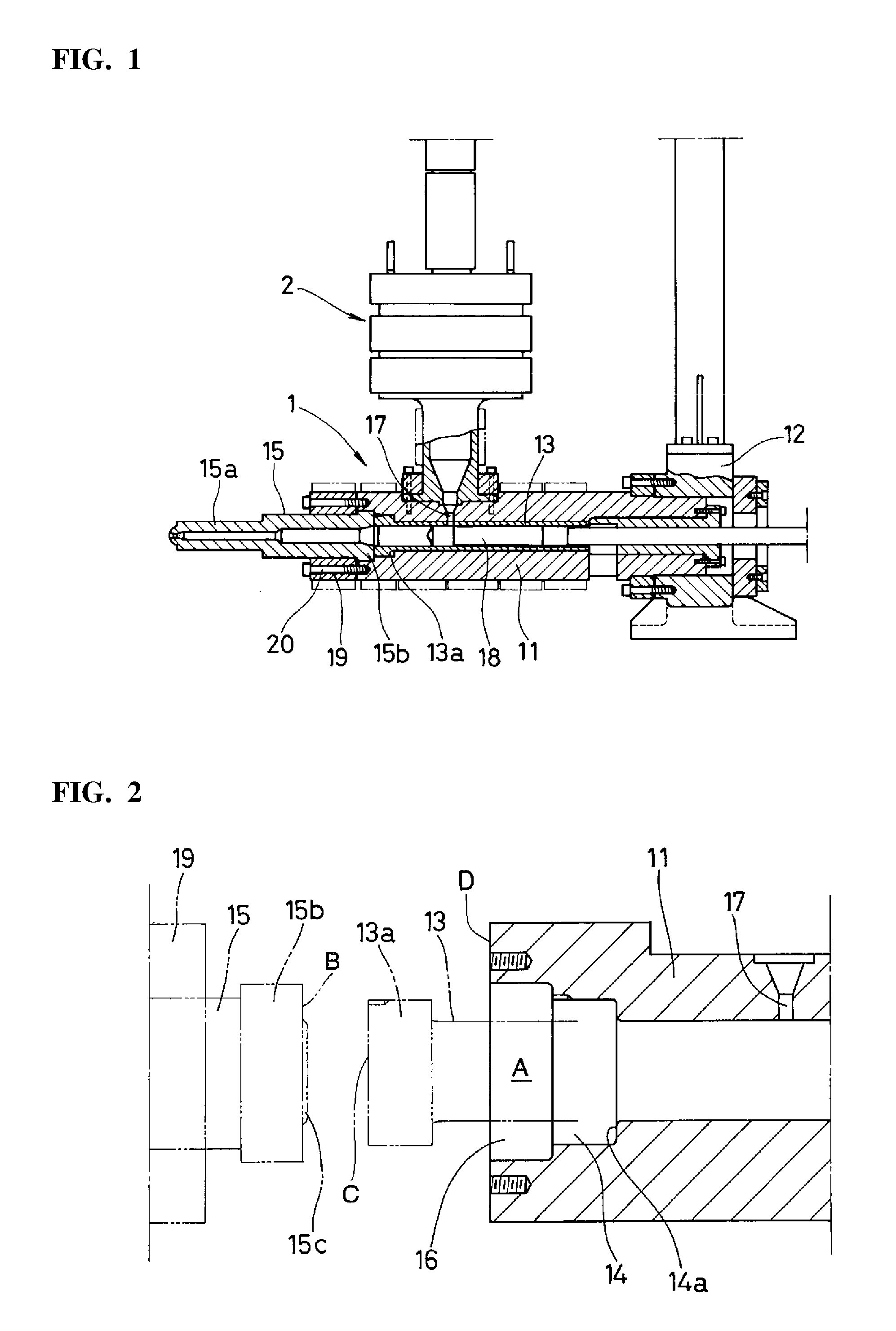
[0030]In FIGS. 1 to 4, the reference numeral 1 denotes an injection cylinder, which is horizontally placed on a not-shown base with the rear end of its cylinder body 11 passed through and fixed to a holding plate 12. The cylinder body 11 has heating means on its periphery. The reference numeral 2 denotes a material melting and storing unit which is arranged on the front part of the cylinder body 11.

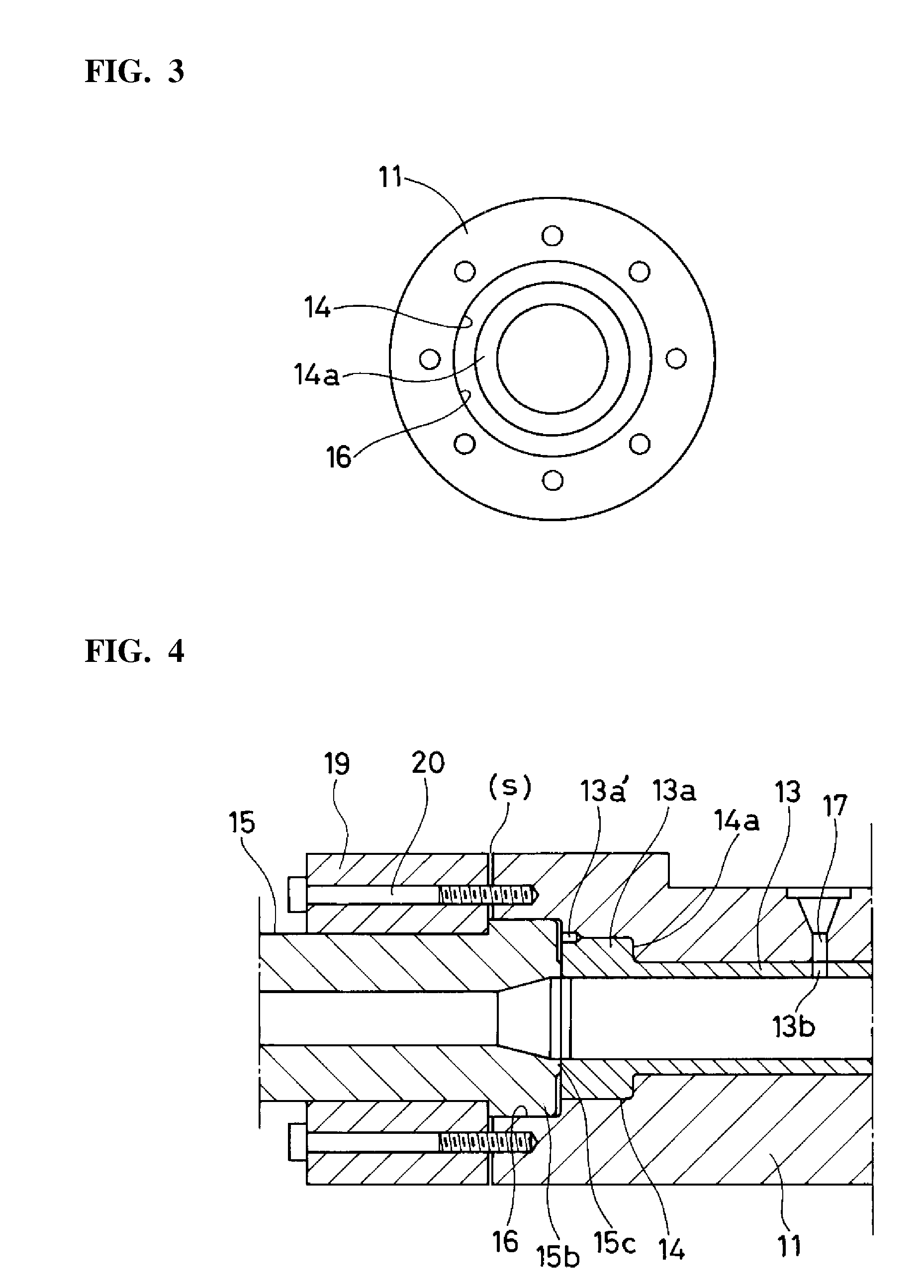
[0031]The cylinder body 11 is made of a cylinder having a first fitting part 14 and a second fitting part 16 in an opening A in its front end. A flange 13a of a cylinder liner 13 is to be fitted to the first fitting part 14, and a flange 15a of a nozzle member 15 is to be fitted to the second fitting part 16. A feed opening 17 is formed in the top of the front part of the cylinder body 11. As will be described, the cylinder liner 13 is passed through this cylinder body. The inner wall of this cylinder liner 13 forms a cylinder hole, into which a plunger 18 is inserted so as to be capable ...


PUM

PropertyMeasurementUnit
Thicknessaaaaaaaaaa
Diameteraaaaaaaaaa
Strengthaaaaaaaaaa

Abstract

Leakage of molten metal material from between a cylinder body having a tight-fitting liner and a nozzle member of an injection apparatus is prevented through the interaction of the nozzle member and a coupling ring with the liner.

Description

BACKGROUND OF THE INVENTION[0001]1. Field of the Invention[0002]The invention relates to an injection cylinder in an injection apparatus for molding a metal material, wherein a molten metal material is injected into a mold from a front nozzle by using a plunger.[0003]2. Description of the Related Art[0004]Injection apparatuses that have been used for molding a metal material are classified into screw type and plunger type. Both types have an injection cylinder of almost the same basic configuration, with only differences in the means for melting and injecting the metal material.[0005]Screw type injection apparatuses have a cylinder body that has a nozzle member attached to its front end and a feed opening formed in its rear top. Powdered metal material charged through the feed opening is heated to melt before it reaches the front part of the cylinder body by screw rotation. The molten material is measured (accumulated) in the front part of the cylinder body by retreating the screw, ...

Claims


Application Information

Patent Timeline
IPC IPC(8): B22D17/00
CPCB22D17/203B22D17/22B22D41/00B23P15/24B22D17/04
Inventor KODA, TOSHIYASUMIYAGAWA, MAMORUTAKEUCHI, YASUHIKO
Owner NISSEI PLASTIC IND CO LTD
Why Eureka
Try Eureka