Structure mounting an electricity storage pack on a vehicle
- Summary
- Abstract
- Description
- Claims
- Application Information
AI Technical Summary
Benefits of technology
Problems solved by technology
Method used
Image
Examples
first embodiment
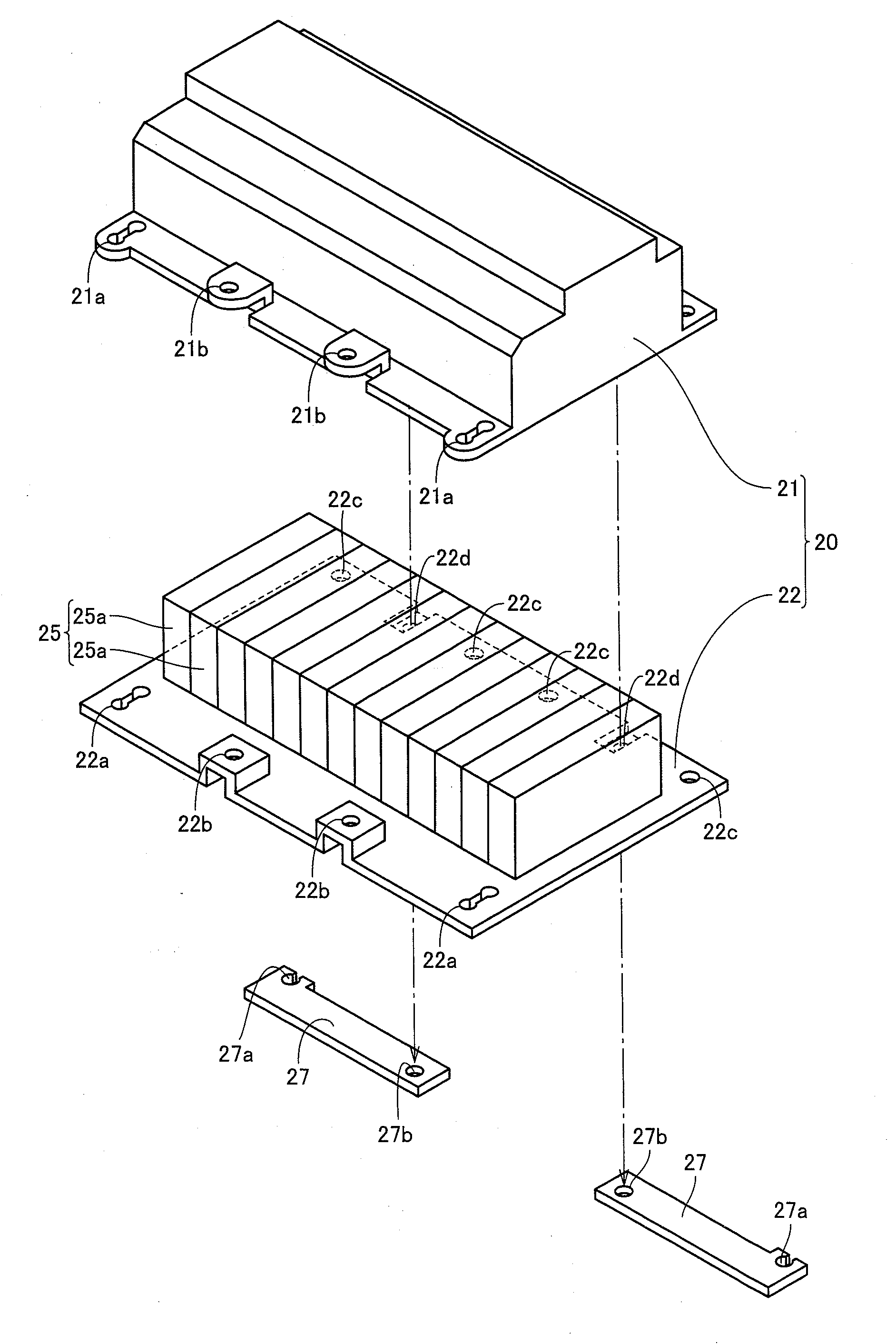
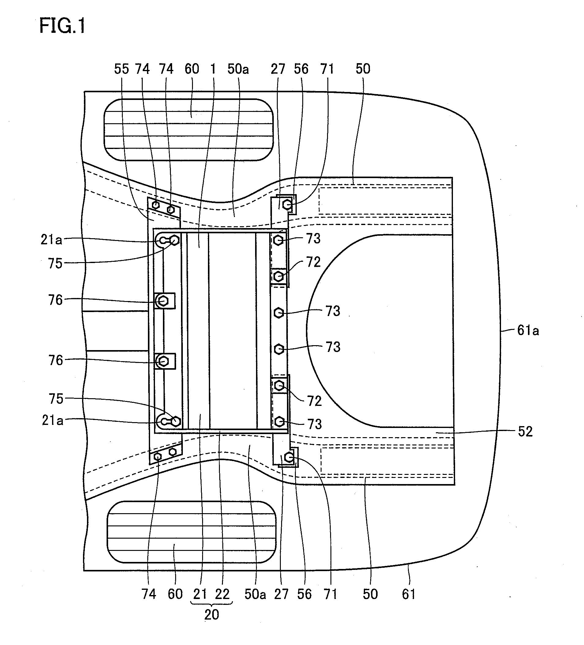
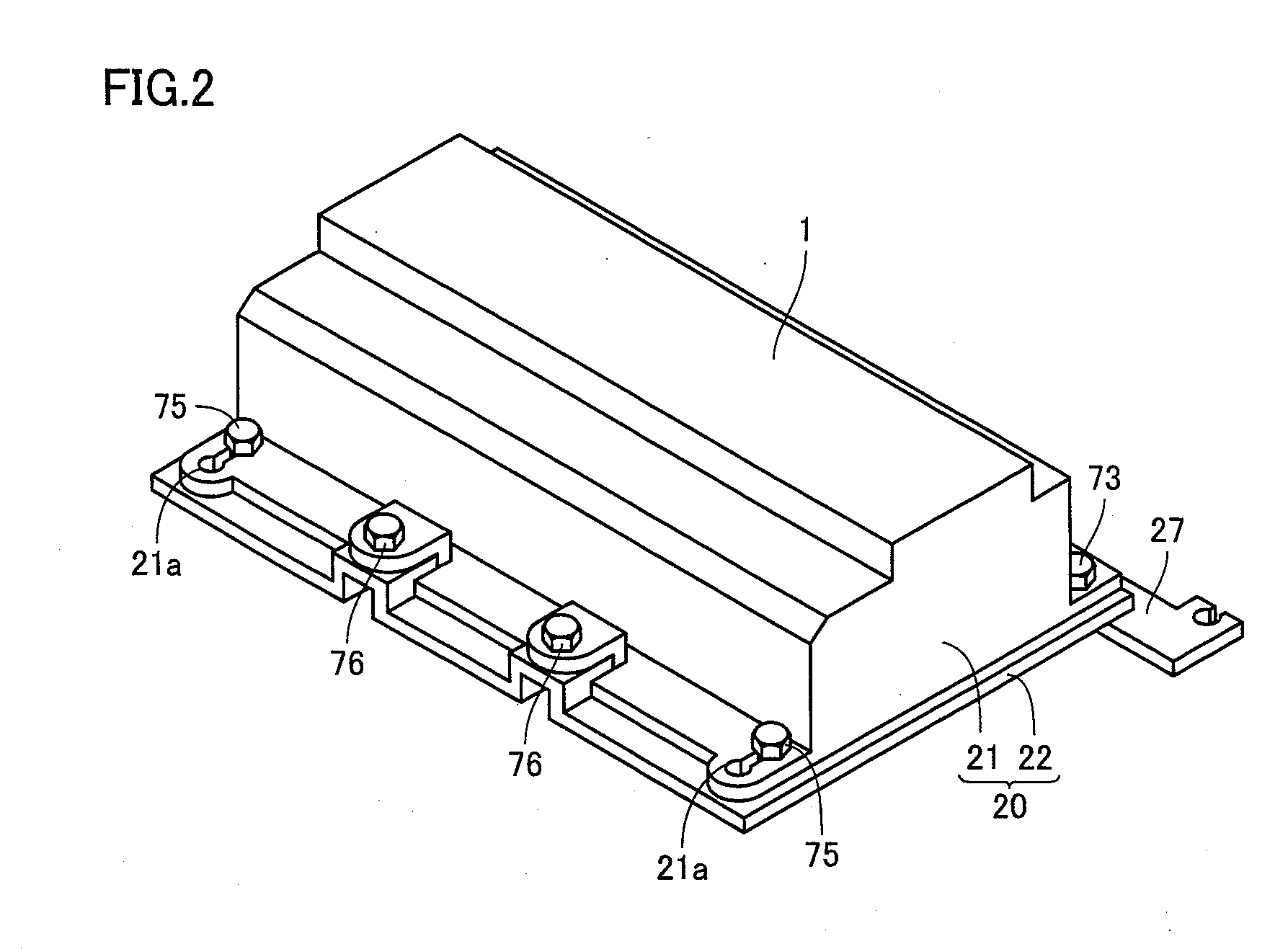
[0041]Reference will now be made to FIG. 1 to FIG. 9 to describe a structure mounting an electricity storage pack on a vehicle in a first embodiment of the present invention.
[0042]A secondary battery, a capacitor or similar electricity storage equipment is accommodated in a case and thus mounted in a vehicle. In the present invention, equipment including the case and the electricity storage equipment accommodated in the case will be referred to as an electricity storage pack. The electricity storage pack may include other internal components including such as a cooling device such as a cooling duct, a cooling fan and the like for cooling the electricity storage equipment, electronics converting power, and the like.
[0043]FIG. 1 is a schematic cross section of the portion of the battery pack in the present embodiment. FIG. 1 shows a rear portion of a vehicular body. In the present invention a so-called sedan vehicle will be described. The vehicle includes a body 61. Body 61 is formed ...
second embodiment
[0077]With reference to FIG. 10, the present invention in a second embodiment provides a structure mounting an electricity storage pack on a vehicle, as will be described hereinafter. The present embodiment provides a structure mounting an electricity storage pack on a vehicle, that supports the electricity storage pack's front portion by a structure different from that described in the first embodiment.
[0078]FIG. 10 is a schematic cross section of a structure mounting a battery pack on a vehicle in the present embodiment. In the present embodiment the structure mounting a battery pack on a vehicle employs four securing members to secure a battery pack to a support member.
[0079]The structure mounting a battery pack on a vehicle includes a securing member implemented as a front bracket 45 disposed at a front end of a battery pack 2. Battery pack 2 includes an upper case 41 and a lower case 42. Upper case 41 and lower case 42 are fastened together by bolts 73, 77.
[0080]Front bracket 4...
third embodiment
[0083]With reference to FIG. 11 to FIG. 14B, the present invention in a third embodiment provides a structure mounting (or attaching) an electricity storage pack to a vehicle, as will be described hereinafter.
[0084]With reference to FIG. 11, the present embodiment provides a structure mounting an electricity storage pack on a vehicle, that has an electricity storage pack implemented as a battery pack 3 having an end closer to the front side of the vehicular body that is supported by side member 50 via mount 55 and floor member 52, and an end closer to the rear side of the vehicular body that is supported by side member 50 via a mount 56a and floor member 52, rather than rear bracket 27 described in the first embodiment. The remainder in configuration similar to that of the first embodiment will be identically labeled and will not be described repeatedly.
[0085]The present embodiment provides battery pack 3 including an upper case 301 and a lower case 302. Similarly as has been descri...
PUM
 Abstract
Description
Claims
Application Information
 - R&D
- Intellectual Property
- Life Sciences
- Materials
- Tech Scout
- Unparalleled Data Quality
- Higher Quality Content
- 60% Fewer Hallucinations
Browse by: Latest US Patents, China's latest patents, Technical Efficacy Thesaurus, Application Domain, Technology Topic, Popular Technical Reports.
© 2025 PatSnap. All rights reserved.Legal|Privacy policy|Modern Slavery Act Transparency Statement|Sitemap|About US| Contact US: help@patsnap.com


