
Apparatus, system, and method for a high efficiency redundant power system

Active Publication Date: 2009-07-02
TWITTER INC
View PDF4 Cites 38 Cited by
  • Summary
  • Abstract
  • Description
  • Claims
  • Application Information

AI Technical Summary

Benefits of technology

[0010]From the foregoing discussion, it should be apparent that a need exists for an apparatus, system, and method that provide high efficiency redundant power supplies for power output less than about 50% of the capacity of the power supplies. Beneficially, such an apparatus, system, and method would increase the efficiency of redundant power supplies operated in parallel while still allowing for efficient fault recovery by providing redundancy protection and while meeting hold-up time requirements.

Problems solved by technology

However, if both power supplies are sharing the load and the load is at full load, each power supply provides only 50%, which is less efficient than a single power supply operating at 100%.
This is even more problematic because each power supply is operating at less than 50% where efficiency degrades rapidly.
The situation is even worse if there are more than two power supplies in parallel.
Conventional art addresses this problem by completely shutting down one of two redundant power supplies when only one power supply is needed or when using two power supplies in parallel is more inefficient than operating a single power supply.
However, a problem with this solution is that by completely shutting down one of the redundant power supplies, the power supply that is shut down is typically unable to recover quickly enough in the event of a failure of the other power supply to prevent a momentary power failure in a system receiving power from the power supplies.
For example, if the power supplies are providing power to a computer system, and one of the power supplies fails while the other is shut down, the computer system may experience errors or a complete failure before the redundant power supply is able to restart and begin providing power to the computer system.
However, if the capacitors are too small, there may not be a long enough hold-up time for a backup power supply to start up and begin providing power.
Conversely, if the capacitors are too large, then too much time may be required to charge up the capacitors of a power supply being started up prior to providing power to a load before the voltage regulated by the power supplies sags to an unacceptable level.

Method used


Image

  • Apparatus, system, and method for a high efficiency redundant power system
  • Apparatus, system, and method for a high efficiency redundant power system
  • Apparatus, system, and method for a high efficiency redundant power system

Examples


Embodiment Construction

[0031]Many of the functional units described in this specification have been labeled as modules, in order to more particularly emphasize their implementation independence. For example, a module may be implemented as a hardware circuit comprising custom VLSI circuits or gate arrays, off-the-shelf semiconductors such as logic chips, transistors, or other discrete components. A module may also be implemented in programmable hardware devices such as field programmable gate arrays, programmable array logic, programmable logic devices or the like.

[0032]Modules may also be implemented in software for execution by various types of processors. An identified module of executable code may, for instance, comprise one or more physical or logical blocks of computer instructions which may, for instance, be organized as an object, procedure, or function. Nevertheless, the executables of an identified module need not be physically located together, but may comprise disparate instructions stored in d...


PUM


Abstract

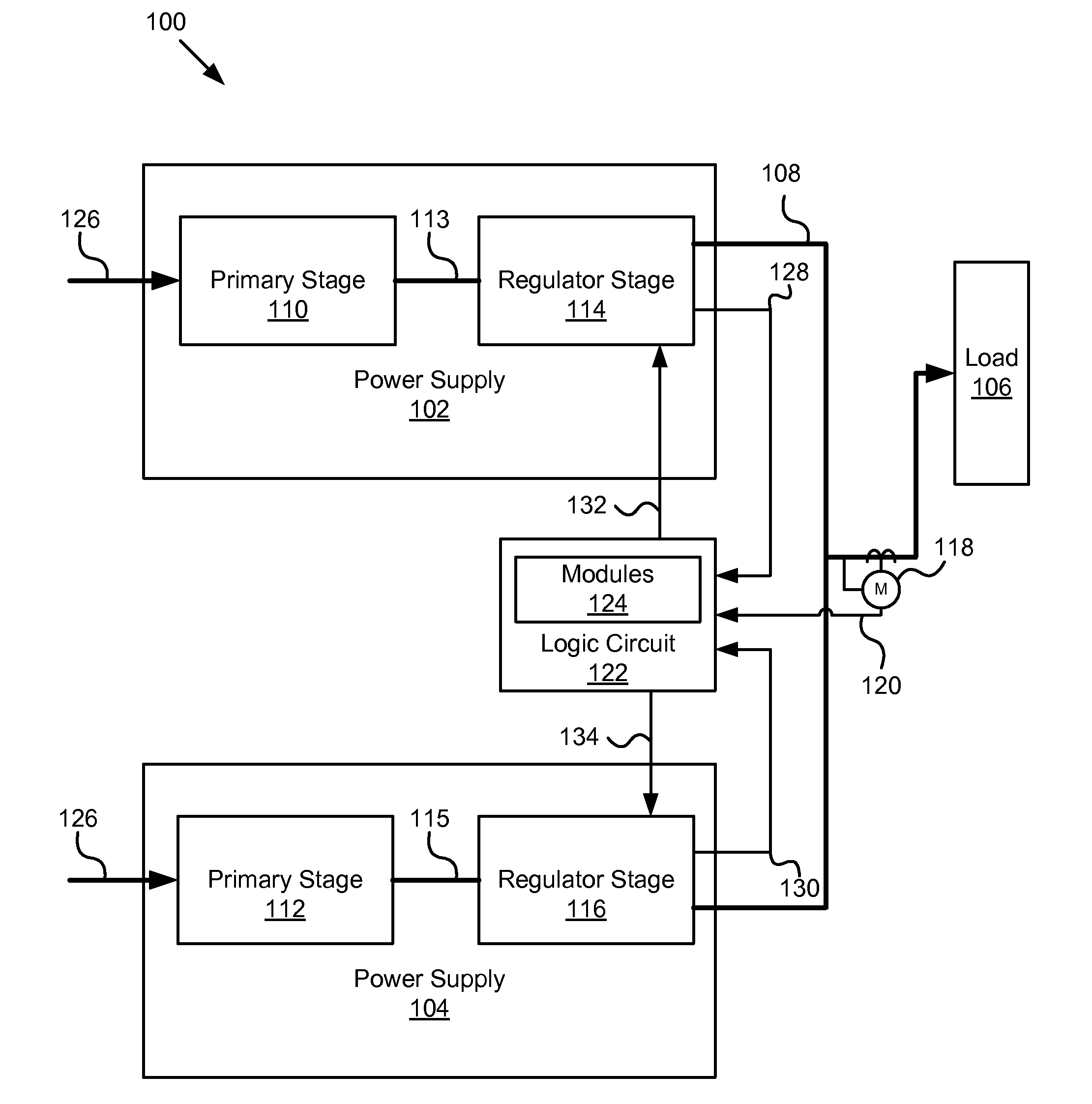
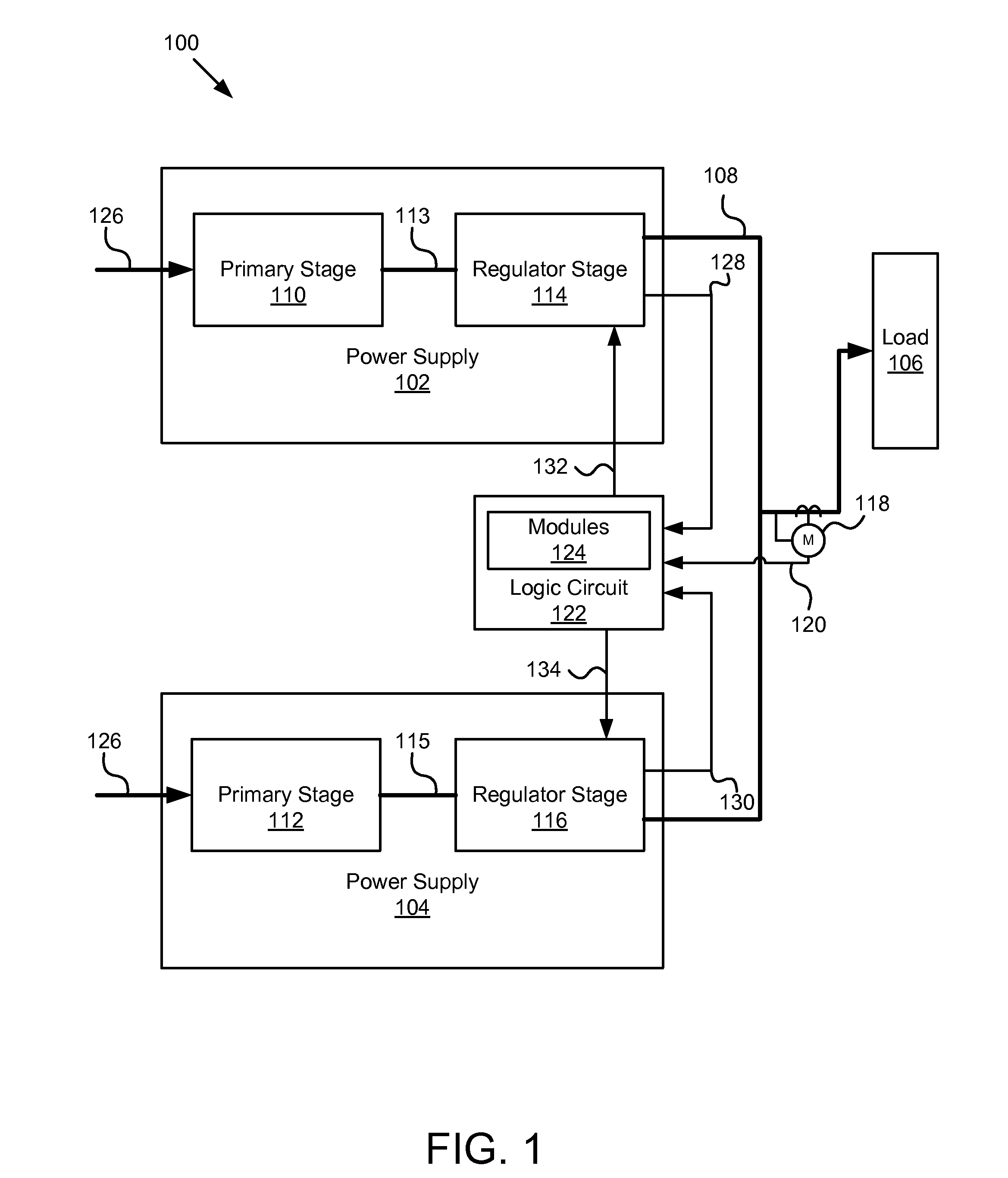
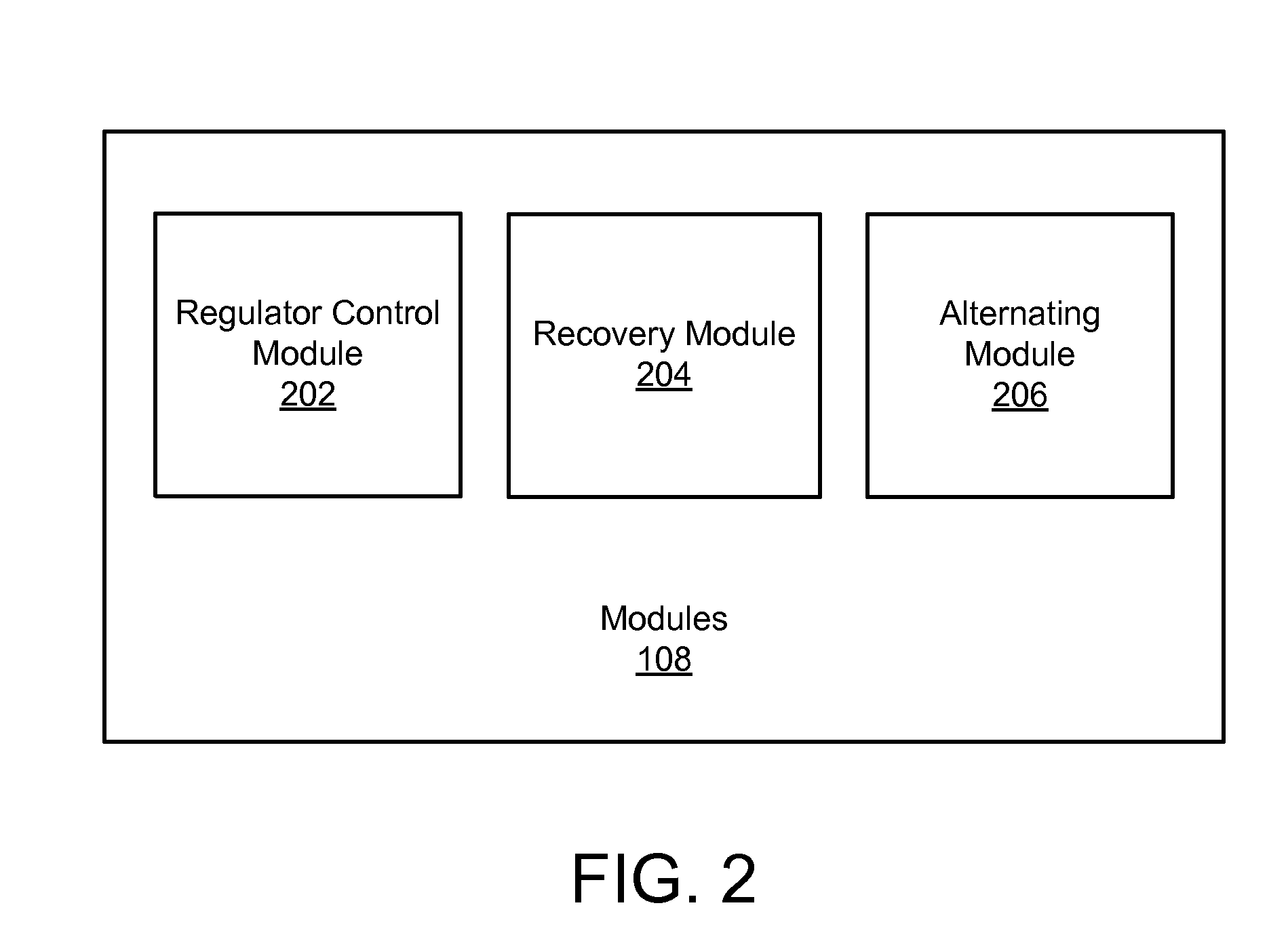
An apparatus, system, and method are disclosed for a high efficiency redundant power system. First and second power supplies are connected in parallel to power a load. Each power supply includes a primary stage and a regulator stage. Each primary stage regulates voltage on an internal bus that is input for each regulator stage. Each regulator stage regulates a regulated bus connected to the load. A power meter detects power provided to the load and determines if the provided power is below a predefined power threshold. A regulator control module shuts down the regulator stage of the first power supply after the provided power falls below the predefined power threshold so the second power supply powers the load and the primary stage of the first power supply remains operational. A recovery module starts up the regulator stage of the first power supply after failure of the second power supply.

Description

BACKGROUND OF THE INVENTION[0001]1. Field of the Invention[0002]This invention relates to power supplies, and more particularly relates to implementing redundant power supplies for increased efficiency at low power output.[0003]2. Description of the Related Art[0004]A power supply, sometimes known as a power supply unit or PSU, is a device or system that supplies electrical or other types of energy to an output load or group of loads. A power supply, in some embodiments may be configured to convert power in one form to another form, such as converting AC power to DC power. The regulation of power supplies is typically done by incorporating circuitry to tightly control the output voltage or current of the power supply to a specific value. The specific value is closely maintained despite variations in the load presented to the power supply's output, or any reasonable voltage variation at the power supply's input.[0005]For example, in an electrical device such as a computer, the power ...

Claims


Application Information

Patent Timeline
IPC IPC(8): H02J9/00
CPCH02J1/10H02J9/06
Inventor DISHMAN, CECIL C.LINDFORS, EINO A.MALIK, RANDHIR S.NGUYEN, TRUNG M.
Owner TWITTER INC
Features
  • Generate Ideas
  • Intellectual Property
  • Life Sciences
  • Materials
  • Tech Scout
  • Unparalleled Data Quality
  • Higher Quality Content
  • 60% Fewer Hallucinations
Learn More