State of Charge Equalizing Device and Assembled Battery System Including Same

a technology of state of charge equalizing and battery system, which is applied in the direction of ac network load balancing, instruments, transportation and packaging, etc., can solve the problems of increasing manufacturing cost, complex structure, and inability to achieve high accuracy in the equalization process, and achieve the effect of higher equalization process accuracy

a technology of state of charge equalizing and battery system, which is applied in the direction of ac network load balancing, instruments, transportation and packaging, etc., can solve the problems of increasing manufacturing cost, complex structure, and inability to achieve high accuracy in the equalization process, and achieve the effect of higher equalization process accuracy

US20090167248A1Active Publication Date: 2009-07-02SANYO ELECTRIC CO LTD

Image

  • State of Charge Equalizing Device and Assembled Battery System Including Same
  • State of Charge Equalizing Device and Assembled Battery System Including Same
  • State of Charge Equalizing Device and Assembled Battery System Including Same

Examples


first embodiment

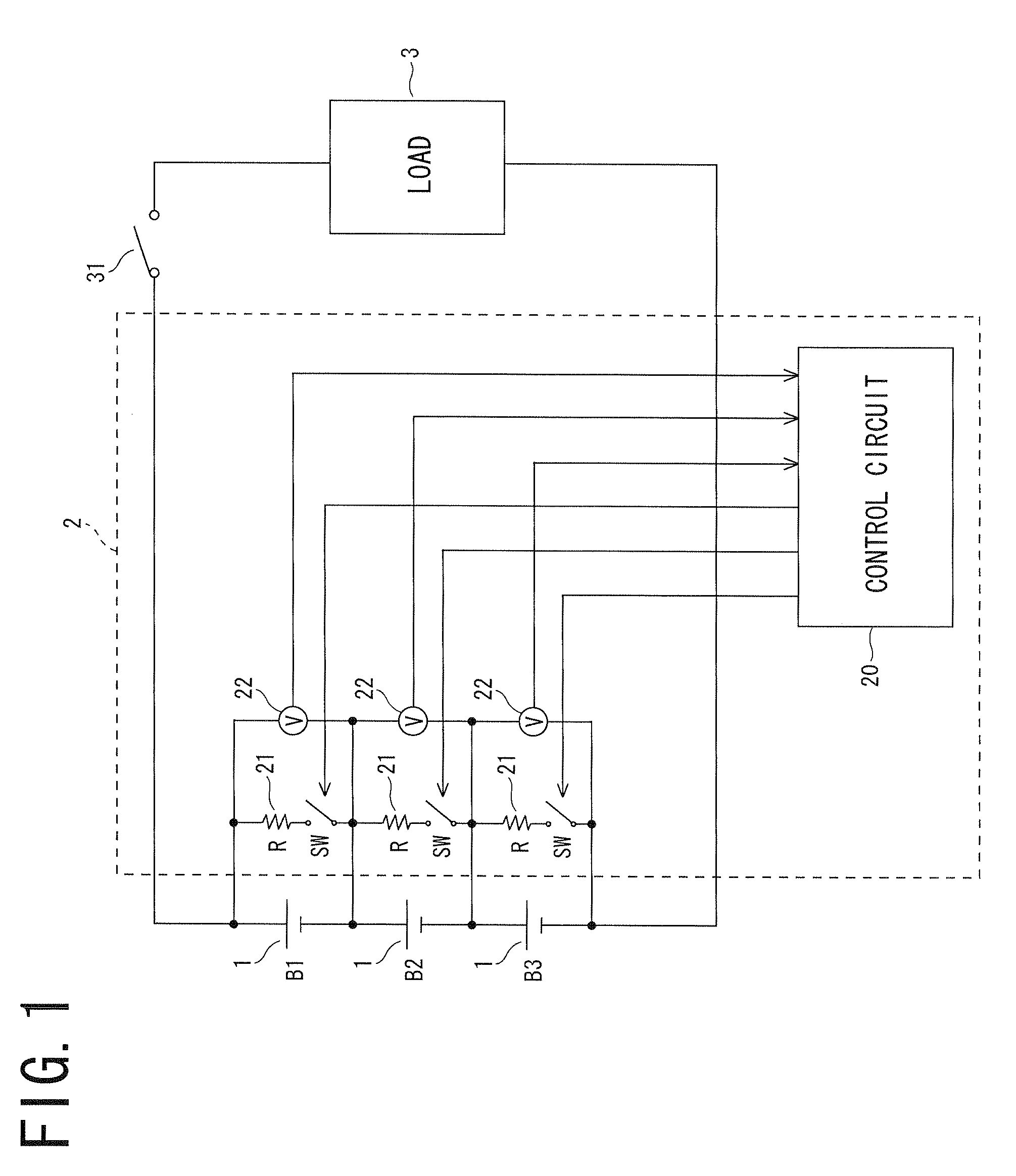
[0046]As shown in FIG. 1, a battery system according to the present invention comprises an assembled battery comprising a plurality of cells 1 including a lithium ion secondary cell (three cells in the example of the figure) connected to each other in series, and a state of charge equalizing device 2 equalizing a state of charge of the assembled battery. It is possible to supply electrical power from the assembled battery to a load 3.

[0047]A power supply path from the assembled battery to the load 3 includes an opening and closing switch 31. When a user operates an ignition switch, which is not shown in the figure, to turn it on, the opening and closing switch 31 closes and the power supply from the assembled battery to the load 3 starts, while when a user operates the ignition switch to turn it off, the opening and closing switch 31 opens and the power supply from the assembled battery to the load 3 stops.

[0048]A discharge circuit 21 comprising a resistor R and a switch SW connecte...

second embodiment

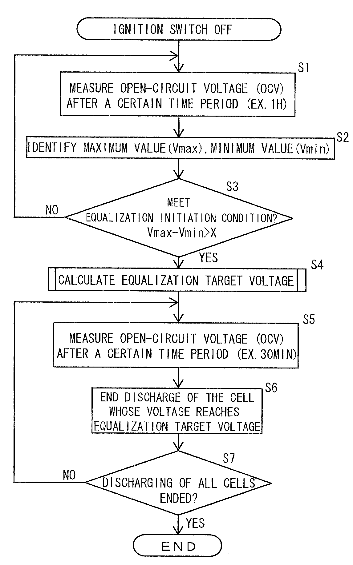
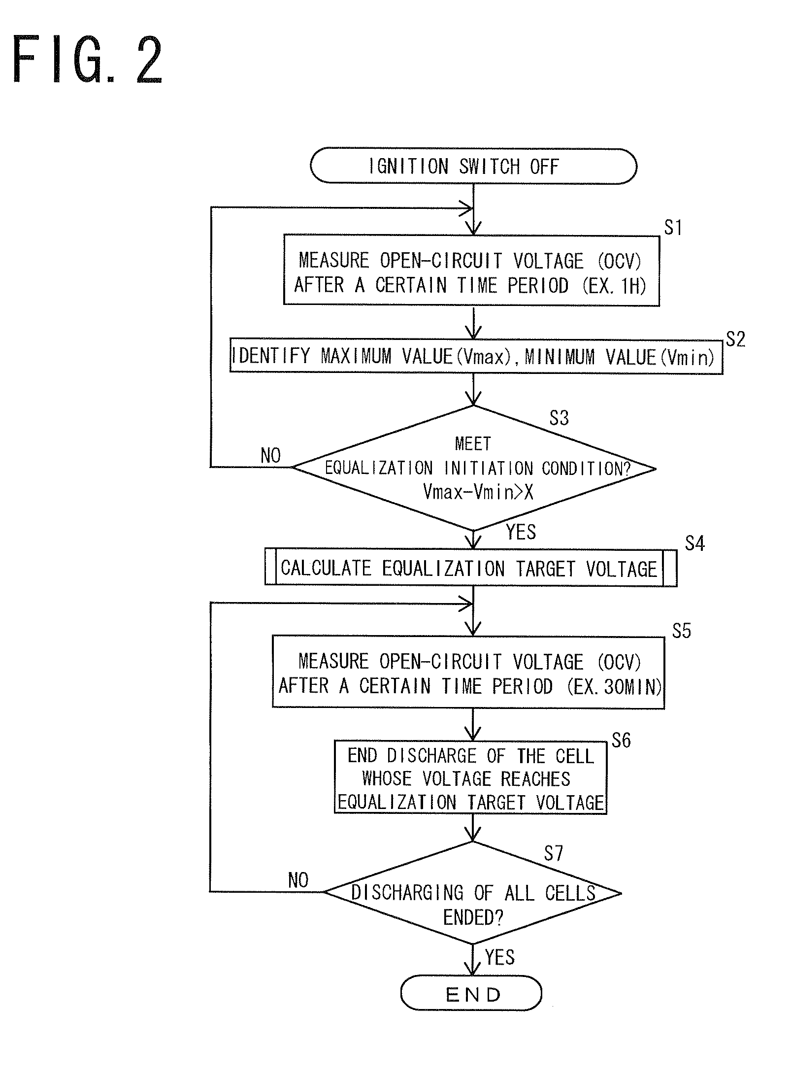
[0063]In the state of charge equalizing device of the first embodiment, the equalization target voltage is corrected after the switches of all the discharge circuits connected to the cells which need to be discharged are set to ON. In contrast, in the state of charge equalizing device of this embodiment, the switches of the discharge circuits connected to the cells which need to be discharged are set to ON in descending order in voltage starting with the cell with the highest voltage, and the equalization target voltage is corrected every time the switch of one discharge circuit is set to ON.

[0064]The structure of the state of charge equalizing device of this embodiment is the same as the state of charge equalizing device of the first embodiment shown in FIG. 1 except for the control circuit. Therefore, the description thereof is omitted. Also, the entire procedure of the equalization process performed by the control circuit is the same as the procedure of the first embodiment shown...


PUM


Abstract

A state-of-charge equalizing device equalizes the state of charge of each of cells connected in series to form an assembled battery, and comprises charging / discharging circuits connected in parallel to the respective cells to discharge and / or charge the respective cells, voltage measurement circuits connected to the respective charging / discharging circuits to measure the voltages across the respective cells, and a control circuit. The control circuit comprises a unit calculating an equalization target voltage based on the measured voltages before the charge or discharge starts, a unit starting discharging / charging the cells having a voltage thereacross different from the target voltage, a unit correcting the target voltage to thereby calculate a corrected equalization target voltage for each of those cells based on the difference between the measured voltages before and at a certain time period after the charging / discharging, and a unit ending the discharging / charging when the measured voltage reaches the corrected target voltage.

Description

[0001]The Japanese application Number 2007-338171, upon which this patent application is based, is hereby incorporated by reference.BACKGROUND OF THE INVENTION[0002]1. Field of the Invention[0003]The present invention relates to devices equalizing the states of charge of a plurality of cells that form an assembled battery, and assembled battery systems including the devices.[0004]2. Description of Related Art[0005]In recent years, an assembled battery has been widely used, for example an assembled battery including a plurality of lithium-ion secondary cells connected in series is used in a hybrid vehicle as a power source. Discharge power of an assembled battery is limited by a cell with the lowest state of charge (SOC) among a plurality of cells that form the assembled battery. Therefore, performance of the assembled battery decreases due to the variation of SOC of the plurality of cells that form the assembled battery. Accordingly, an equalization process is required to limit the ...

Claims


Application Information

Patent Timeline
02 Jul 2009
Publication
US20090167248A1
IPC
H02J7/00; H02J7/02
CPC
Y02T10/7055; H02J7/0016; Y02T10/70
Inventors
MURAO, HIROYA; KIRIMOTO, MIKA