Resolver apparatus and angle detection device and method of resolver

a technology of resolver and detection device, which is applied in the direction of liquid/fluent solid measurement, digital computer details, instruments, etc., to achieve the effect of easy correction of the detection error of the resolver

Active Publication Date: 2009-07-02
TOSHIBA MASCH CO LTD
View PDF5 Cites 38 Cited by
  • Summary
  • Abstract
  • Description
  • Claims
  • Application Information

AI Technical Summary

Benefits of technology

[0027]According to the present invention, by applying frequency analysis, for example, a Fourier transform, detection errors of individual resolvers can be correctly calculated. Then, by correcting the detected angle signal by using the found detection error, a correct angle detection signal can be pr

Problems solved by technology

Detection error in a resolver is caused by the imbalance of windings in the resolver and mutual interference of w

Method used


Image

  • Resolver apparatus and angle detection device and method of resolver
  • Resolver apparatus and angle detection device and method of resolver
  • Resolver apparatus and angle detection device and method of resolver

Examples


Embodiment Construction

[0046]An angle detection device of a resolver according to an embodiment of the present invention will be explained with reference to the attached drawings.

Resolver and Angle Detection Device

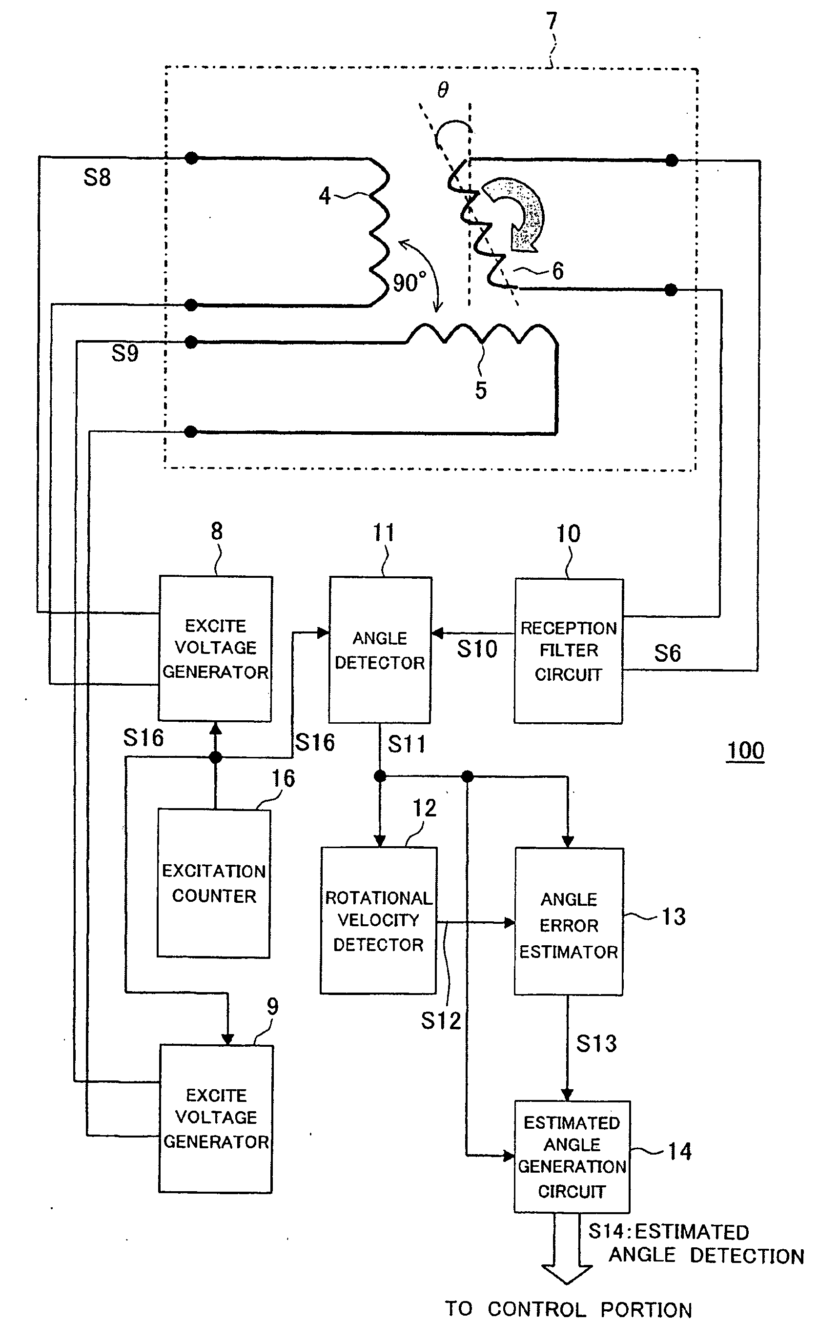
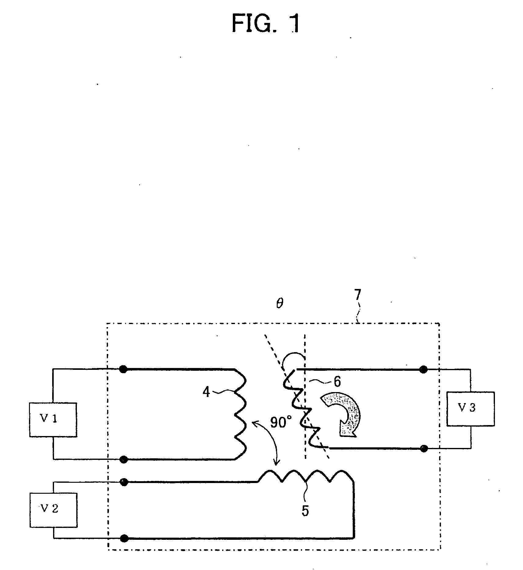
[0047]FIG. 6 is a view of the configuration of a resolver and an angle detection device according to an embodiment of the present invention. In FIG. 6, the resolver body 7, in the same way as explained with reference to FIG. 1, has an SIN winding 4 and a COS winding 5 arranged mechanically offset by 90 degrees to a stator side and has a rotor winding 6 disposed in the rotating part.

[0048]As resolvers, a two-phase excitation single output system and a single-phase excitation two-output system are known. In a resolver of the two-phase excitation single-phase output system, an SIN winding voltage and a COS winding voltage are applied to the SIN winding 4 and COS winding 5, and a signal corresponding to the rotational angle (or rotational position) of the object for which the rotational angle (or ro...


PUM


Abstract

A resolver apparatus having a high detection precision detecting angle signals from signals detected at a resolver (7) and detecting a velocity signal from the detected angle signals. Utilizing the fact that an error waveform of a resolver is comprised of predetermined n-th order components inherent to the resolver and has reproducibility, an angle error estimator (13) applies a frequency transform, for example, a Fourier transform, to high frequency components of velocity signal including error generated from detected angle signals including error to calculate a magnitude of error for each of a plurality of divided components and combining the calculated errors to reproduce the detected error and generate an error waveform signal. An angle signal correction circuit (14) uses this error waveform signal to correct an angle signal including error detected at the resolver.

Description

CROSS REFERENCES TO RELATED APPLICATIONS[0001]The present invention contains subject matter related to Japanese Patent Application No. 2007-338940 filed in the Japan Patent Office on Dec. 28, 2007, the entire contents of which being incorporated herein by reference.BACKGROUND OF THE INVENTION[0002]1. Field of the Invention[0003]The present invention relates to a resolver apparatus and an angle detection device and method of the same. More specifically, the present invention relates to an angle detection device and method of a resolver raising the detection precision and a resolver apparatus having the angle detection device and a resolver.[0004]2. Description of the Related Art[0005]FIG. 1 is a view of the configuration of a resolver body 7. The resolver body 7 is provided with a SIN winding 4, a COS winding 5 arranged mechanically offset by 90 degrees from this SIN winding 4, and a rotor winding 6. An object of detection of the rotational angle (or rotational position), for example...

Claims


Application Information

Patent Timeline
IPC IPC(8): G01B7/30
CPCG01D5/2073G01D5/24452G01P3/44G01P3/00G01D5/2449G01D18/001
Inventor YOKOKAWA, NARUTOSHI
Owner TOSHIBA MASCH CO LTD
Why Eureka
Try Eureka