
Surveillance system for real-time threat monitoring

a surveillance system and real-time threat technology, applied in the field of threat indication detectors, can solve the problems of high cost of all these methods, inability to train well-trained inspection teams, and threat to the world around us

Inactive Publication Date: 2009-07-02
PORTENDO
View PDF15 Cites 4 Cited by
  • Summary
  • Abstract
  • Description
  • Claims
  • Application Information

AI Technical Summary

Benefits of technology

[0006]The surveillance system according to this invention achieves this and other objects by comprising a network of threat indication detectors, which are distributed with a high coverage and automatically transmit information regarding detected threat indications to one or more common central units. In order to achieve a high coverage, each of the threat indication detectors of the system is adapted both for a mobile location and immobile (stationary) location, or a semi-mobile location, allowing a great flexibility and makes the prediction of the scan more difficult. A threat indication detector can be mounted permanently or detachably in e.g. a building or in a transporting device, and may also be portable, to be carried by personnel, e.g. in the pocket of a uniform. The low cost of a threat indication detector, and the flexible use, allows a high coverage and a good geographic distribution, which, furthermore, is unpredictable. By using existing communication systems, the detected threat indications can be transferred automatically to a central unit, in which e.g. police officers monitor a threat indication picture, which is compiled automatically and continuously and presented e.g. as a map.
[0007]The surveillance system according to this invention intends to detect threat indications, which originates e.g. from explosives, hazardous gases, radioactive material or organisms, and the surveillance system displays a compilation of the threat indications with complete coverage. Thus, the surveillance system according to this invention allows autonomous, continuous and area-covering detection of threat indication; mapping and display of threat indications and their movements in real-time; efficient and non-predictable scanning of large areas and spaces; and a threat indication detection that can be performed to a large extent without any active participation of personnel.

Problems solved by technology

Daily, the world around us is threatened by terrorist organizations attempting e.g. to influence the political direction of the world, by means of various bombing attacks against buildings and people.
All of these methods are very costly and require well-trained inspection teams for handling the dogs and for using the inspection equipment.
Previously known detection systems within this field have several disadvantages, e.g. they involve high costs, require handling and active participation of trained personnel, are not adapted for continuous surveillance, lack real-time reporting to a common surveillance central for a compiled presentation of threats, and have a low area coverage.

Method used


Image

  • Surveillance system for real-time threat monitoring
  • Surveillance system for real-time threat monitoring
  • Surveillance system for real-time threat monitoring

Examples


first embodiment

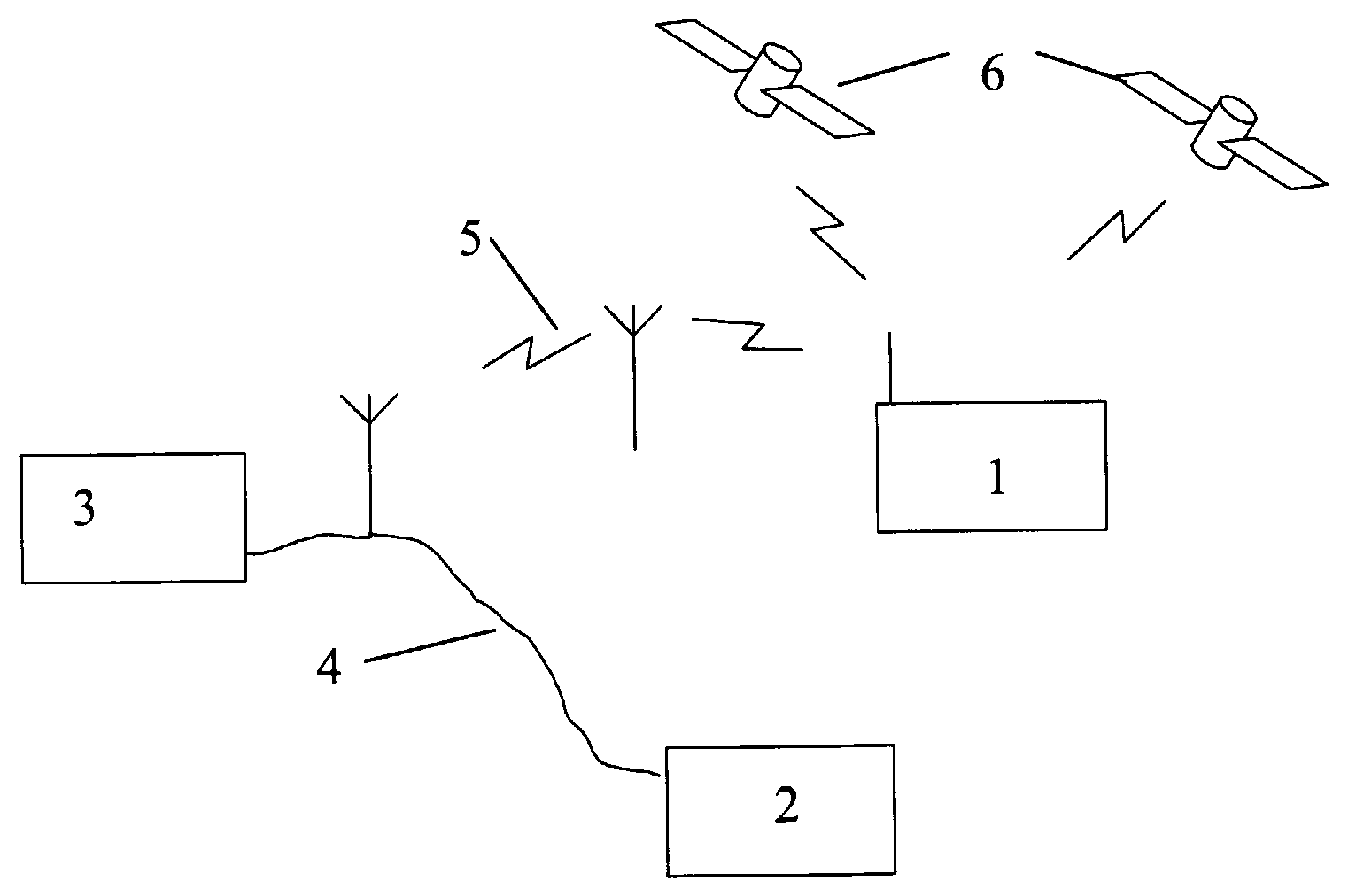
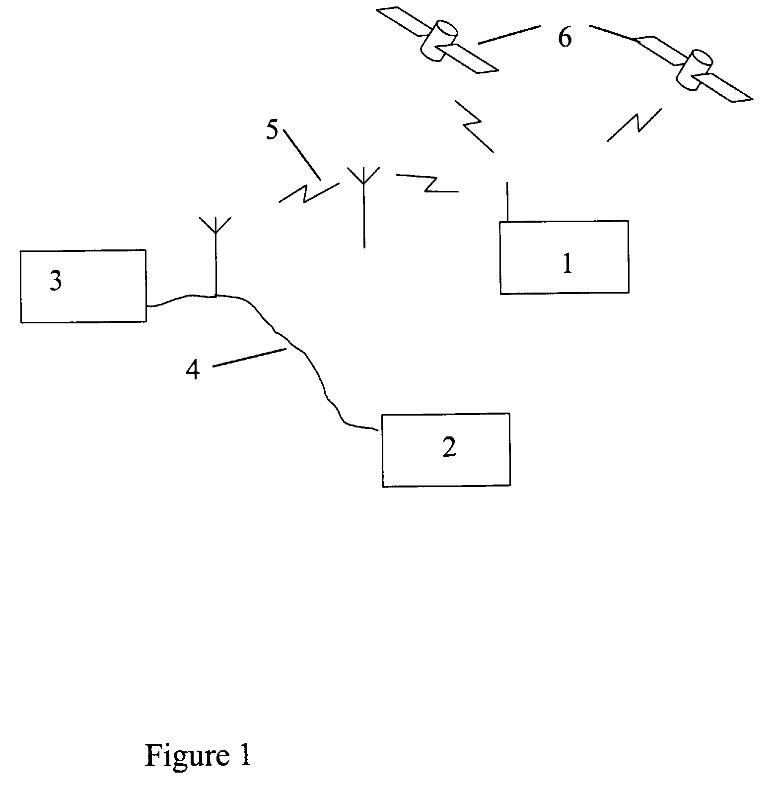
[0018]a system according to this invention is a surveillance system comprising one or more central units 3, to each of which an arbitrary number of threat indication detectors 1 are connected, each designed both for an immobile and a mobile location by being provided with positioning means 6 and a wireless connection 5 with a central unit 3. However, a threat indication detector 1 may also be provided with a wire connection 4 for a permanent connection to a central unit, to be used in an immobile location. A second embodiment of this system further comprises threat indication detectors intended only for an immobile location.

[0019]Each central unit 3 receives threat information transferred automatically from the threat indication detectors 1, 2 within the system, and compiles the information automatically into one common threat indication picture, which is suitably presented, e.g. on a display screen, as a map provided with superimposed threat indication markers, which may be updated...

second embodiment

[0027]A threat indication detector 2 only adapted for immobile locations, may alternatively store data regarding the detector location in the central unit, wherein no active positioning equipment is required.

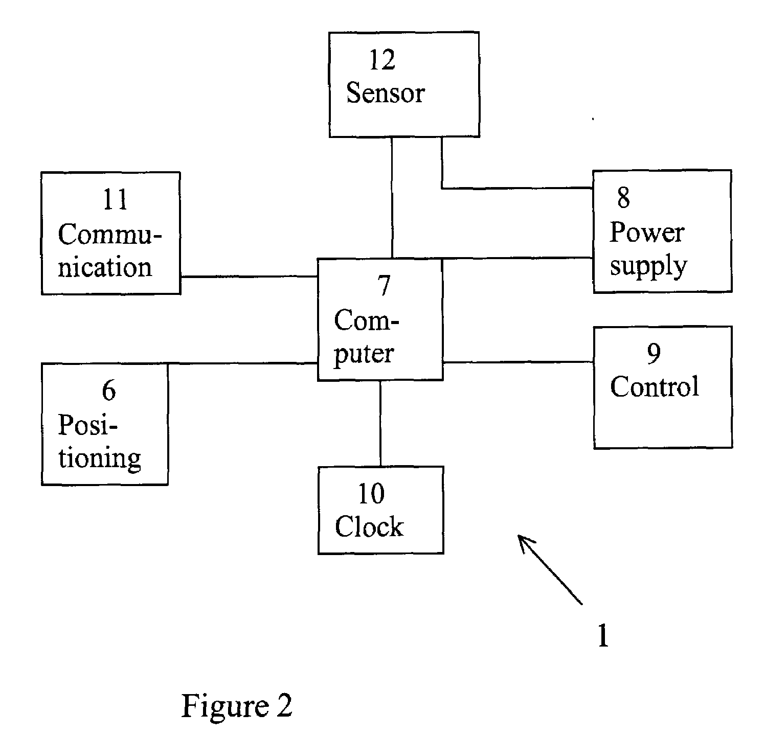
[0028]A threat indication detector 1 adapted for both mobile and immobile locations primarily communicates via a wireless connection, such as by radio communication, but it may, additionally, be provided with an interface for a wire connection to be used in an immobile location. Preferably, the communication is two-way, in order to provide an opportunity for remote control and remote maintenance of the detector.

[0029]A clock 10 in the detector performs time stamping and time control of events, and the clock is synchronized by means of a satellite positioning equipment or a communication link.

[0030]A function supervisor 9 in the detector supervises the operating status, reports error conditions, and resets the detector in case of en emergency error.

[0031]A central unit 3 accordi...


PUM


Abstract

Surveillance system for automatic detection and presentation of threat indications, the system comprising several threat indication detectors and at least one central unit adapted for communication with said threat indication detectors and for presentation of threat images. Threat information signals are transferred automatically from the threat indication detectors to the central unit, and each threat indication detector can be located both immobile, semi-mobile of mobile.

Description

TECHNICAL FIELD[0001]This invention relates to a system for automatic and continuous detection and presentation of threats in real-time, and a threat indication detector adapted to be included in such a system.BACKGROUND OF THE INVENTION AND PRIOR ART[0002]Daily, the world around us is threatened by terrorist organizations attempting e.g. to influence the political direction of the world, by means of various bombing attacks against buildings and people. For this reason, most states are provided with authorities for monitoring and fighting security threats, e.g. the customs, intelligence service and the police. Their surveillance methods mainly consist of intelligence activities, in combination with isolated efforts of special forces trained to detect bombs, gas attacks and similar threats to the security. Normally, the bomb searching will be performed by specially trained dogs, while the custom officers and security personnel at airports and in harbours also use scanners for the sca...

Claims


Application Information

Patent Timeline
IPC IPC(8): B60Q1/00G08B21/00G08B23/00G08B1/08G08BG08B21/12G08B25/00
CPCG08B25/08G08B21/12G08B25/10G08B25/016
Inventor STROMBECK, PIERRESTROMBECK, PETERSVENSSON, DANIELNILSSON, JAN
Owner PORTENDO
Learn More