
Method and system for producing tomographic image by optical tomography

a tomographic image and optical tomography technology, applied in the field of methods and systems for producing optical tomographic images, can solve the problems of low motion-image response characteristic of tomographic images, and achieve the effects of reducing data processing amount, and improving motion-image response characteristi

Active Publication Date: 2009-07-02
KK TOPCON
View PDF1 Cites 3 Cited by
  • Summary
  • Abstract
  • Description
  • Claims
  • Application Information

AI Technical Summary

Benefits of technology

The present invention provides a system and method for producing tomographic images using optical tomography with a low-cost processing unit. The system includes a light source unit that outputs light with a periodically swept wavelength. The light is divided into measurement light and reference light, and the reference light is combined with the reflection light from the measurement target. The interference signals are detected and used to produce the tomographic image. The system can produce tomographic images with higher motion-image response characteristics. The method involves thinning the interference signals, obtaining light intensity information, and updating the tomographic image based on the light intensity information. The system can also include a region division means to divide the region that is scanned with the measurement light into multiple areas and update the tomographic image based on the light intensity information for each area.

Problems solved by technology

Hence, there is a problem that the motion-image response characteristic of the tomographic images is low.

Method used


Image

  • Method and system for producing tomographic image by optical tomography
  • Method and system for producing tomographic image by optical tomography
  • Method and system for producing tomographic image by optical tomography

Examples


Embodiment Construction

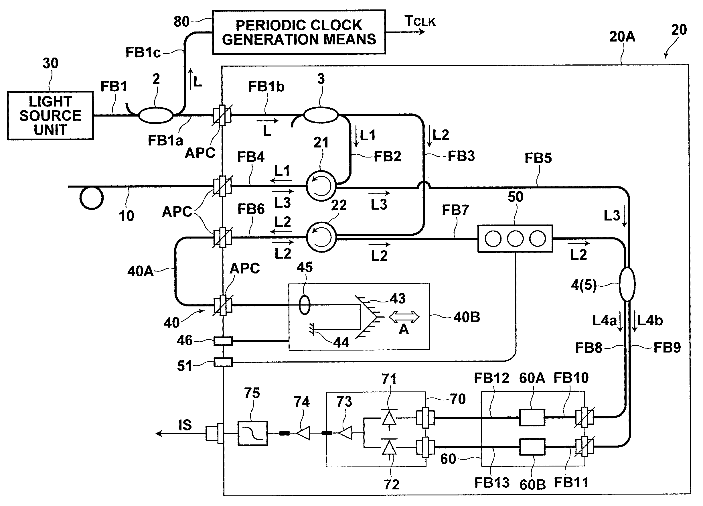
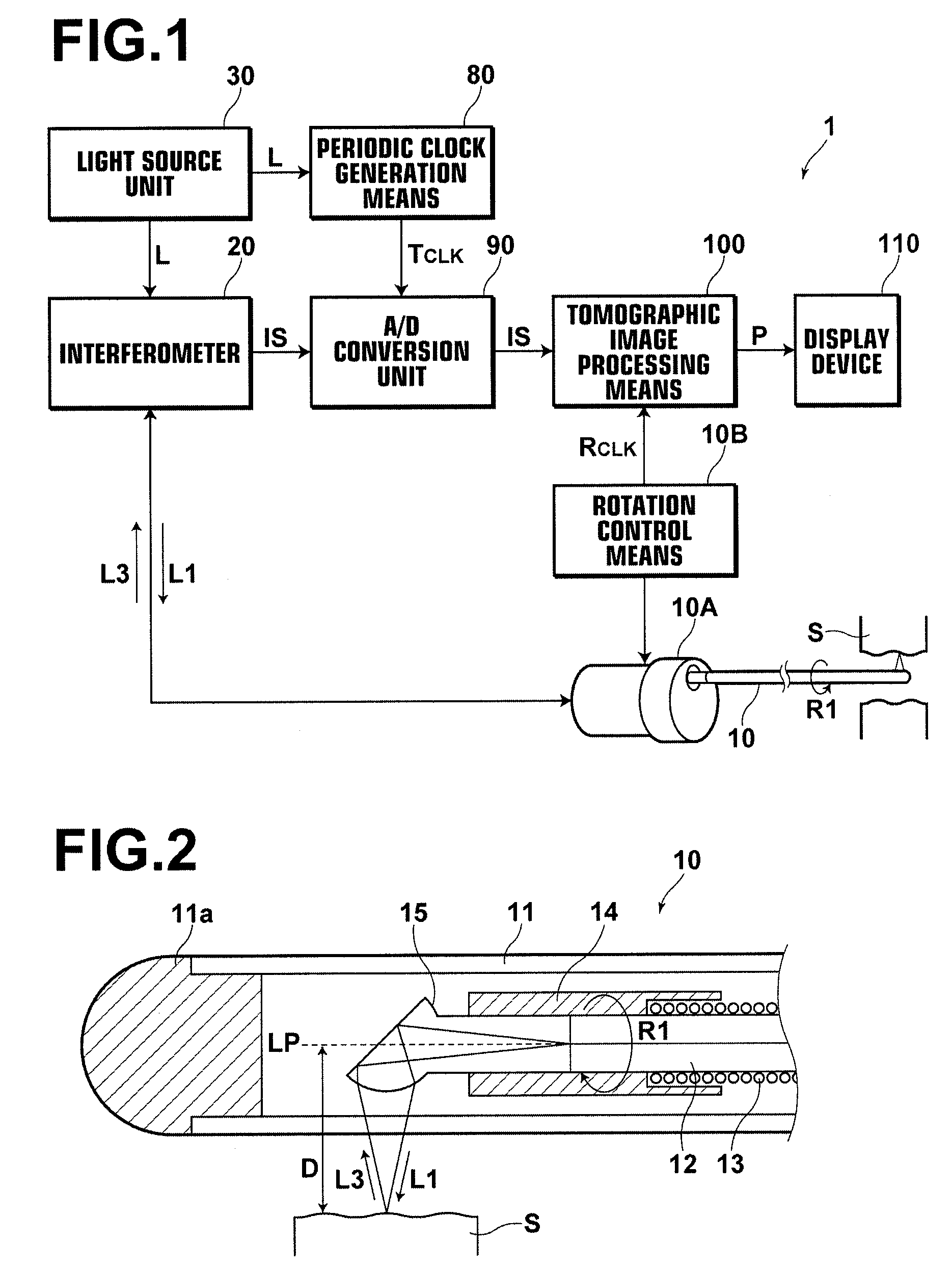
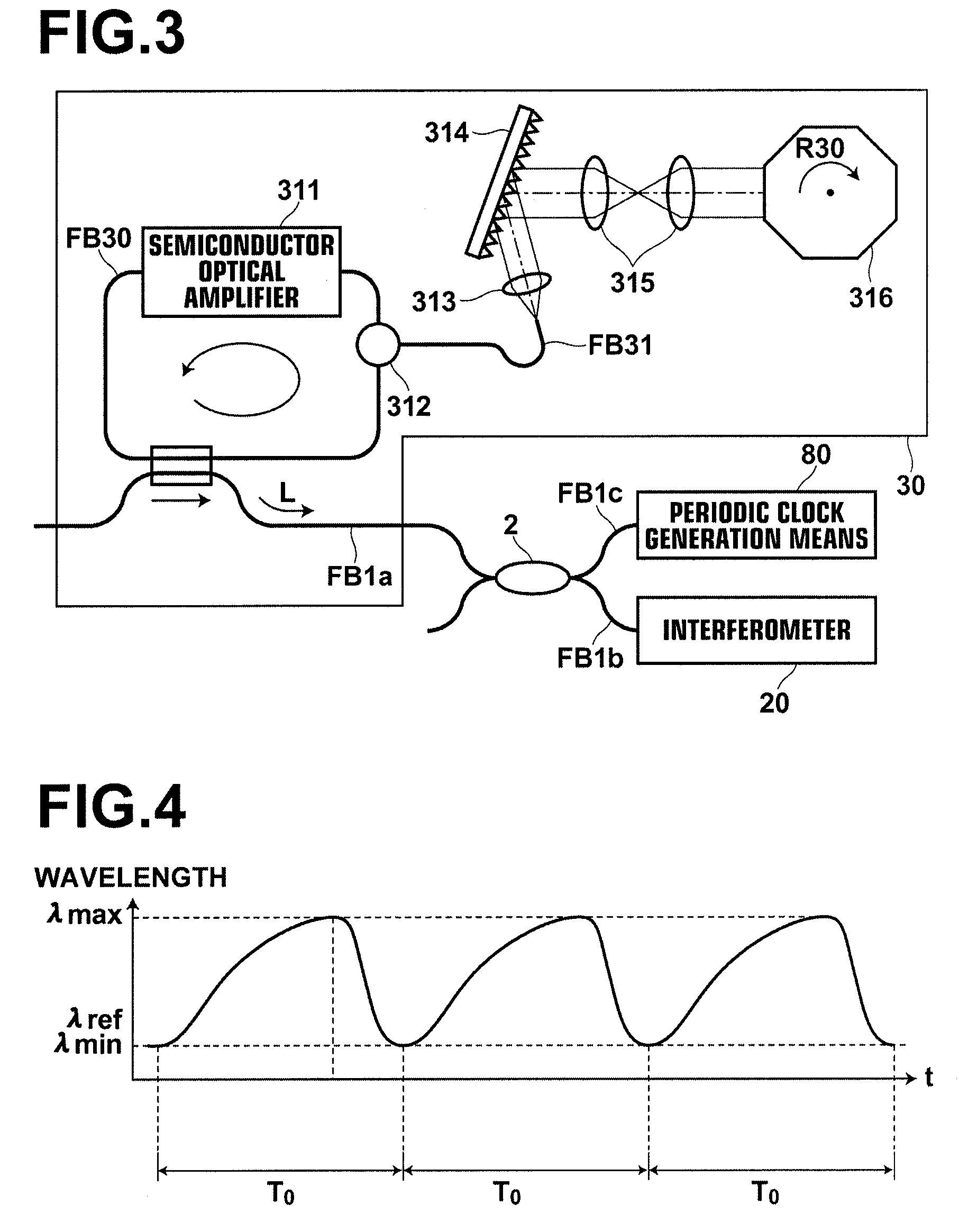
[0052]Hereinafter, embodiments of a system for producing tomographic images by optical tomography according to the present invention will be described with reference to drawings. FIG. 1 is a schematic diagram illustrating the configuration of a system for producing tomographic images by optical tomography according to a preferred embodiment of the present invention. A system 1 for producing tomographic images by optical tomography obtains tomographic images of measurement target S, such as tissue or cells in the body cavities of living organisms (in vivo), by SS-OCT (Swept Source OCT) measurement by inserting an optical probe 10 into the body cavities. The system 1 for producing tomographic images by optical tomography includes the optical probe 10, an interferometer 20, a light source unit 30, a periodic clock generation means 80, an A / D (analog to digital) conversion unit 90, a tomographic image processing means 100, a display device 110 and the like.

[0053]FIG. 2 is a schematic di...


PUM


Abstract

When reflection light, reflected from a measurement target that has been irradiated with measurement light in such a manner to scan the measurement target, and reference light are combined in each wavelength sweep, interference light is detected as interference signals. When a thinning region in which the interference signals obtained by detecting the interference light in each wavelength sweep are thinned so that the interference signals that are used to produce the tomographic image remain is set, thinning is performed on the plurality of interference signals in the thinning region. Light intensity information about the measurement target in the thinning region is obtained, based on the interference signals for the respective wavelength sweeps, the interference signals remaining after thinning. The tomographic image in the thinning region is produced based on the obtained light intensity information.

Description

BACKGROUND OF THE INVENTION[0001]1. Field of the Invention[0002]The present invention relates to a method and a system for producing optical tomographic images by OCT (Optical Coherence Tomography) measurement.[0003]2. Description of the Related Art[0004]Conventionally, ultrasonic diagnostic apparatuses (ultrasonographs) have been used to observe lesions in the body cavities of patients. The ultrasonic diagnostic apparatuses obtain and display ultrasonic tomographic images of the lesions as motion images (video images). For example, in Japanese Unexamined Patent Publication No. 2004-344516, the entire area of an image represented by image data is divided into a plurality of areas, and the image data is updated for each of the divided areas to smoothly update the image.[0005]Further, as a method for obtaining tomographic images of tissue in vivo (in living organisms), apparatuses for obtaining optical tomographic images are used, in some cases, in addition to the ultrasonic diagnosti...

Claims


Application Information

Patent Timeline
Patent Type & Authority Applications(United States)
IPC IPC(8): G01B11/02
CPCG01B9/02004G01B9/02091G01B9/02083G01B2290/70G01B9/02069
Inventor TERAMURA, YUICHIOZAWA, SATOSHI
Owner KK TOPCON
Learn More