Photomask inspection apparatus

a technology of inspection apparatus and mask, which is applied in the field of photomask inspection apparatus, can solve the problems of insufficient sensitivity to inspect a 32-nm generation of mask, easy torn pellicule, and difficult to apply liquid immersion technique, etc., and achieve the effect of improving resolution

Inactive Publication Date: 2009-07-02
LASERTEC CORP
View PDF1 Cites 15 Cited by
  • Summary
  • Abstract
  • Description
  • Claims
  • Application Information

AI Technical Summary

Benefits of technology

[0014]According to a first aspect of the present invention, there is provided a photomask inspection apparatus which observes a pattern provided on a mask substrate of a mask to inspect the mask including an object lens, and a liquid that is present between a last lens in the side closer to the mask of the object lens and the mask. By this means, resolution can be improved.

Problems solved by technology

Because the pellicle 804 is formed of an extremely thin polymer of about 1 μm in thickness, there is the problem that the pellicle is easy to be torn.
Even if an ArF excimer laser of 193.4 nm in wavelength or the like can be used for the mask inspection light source, they will not be enough in sensitivity to inspect a 32-nm generation of masks.
Accordingly, considering the application of the liquid immersion technique to photomask inspection apparatuses as with the exposure technology, the problem below exists, and hence it has been extremely difficult to apply the liquid immersion technique.
Of course, at a stage before applying the pellicle to them in the production process of masks, such liquid immersion technique can be used, but in the photomask inspection where masks finished by applying the pellicle thereto are inspected, the liquid immersion technique cannot be used.
There is the problem that in the conventional photomask inspection apparatus, it is difficult to improve the resolution and sensitivity.

Method used


Image

  • Photomask inspection apparatus
  • Photomask inspection apparatus
  • Photomask inspection apparatus

Examples


embodiment 1

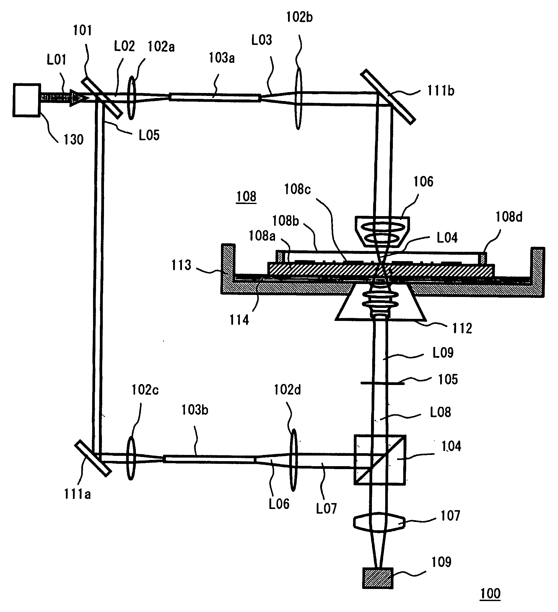
[0065]A photomask inspection apparatus according to embodiment 1 of the present invention will be described with reference to FIG. 1. FIG. 1 shows the configuration of a photomask inspection apparatus 100 according to the present embodiment. As shown in FIG. 1, the photomask inspection apparatus 100 comprises an inspection light source 130, a half mirror 101, lenses 102a to 102d, homogenizing optical systems 103a, 103b, a polarization beam splitter 104, a quarter wavelength plate 105, a condenser lens 106, a projection lens 107, a two-dimensional photosensor 109, mirrors 111a, 111b, an object lens 112, a water bath 113, and pure water 114. The photomask inspection apparatus 100 according to the present embodiment is for inspecting a finished mask 108 comprising a frame 108d provided so as to surround a pattern surface 108c formed on a mask substrate 108a and a pellicle 108b applied to this. In this embodiment, synthetic quartz of about 1.5608 in refractive index is used as the mask ...

embodiment 2

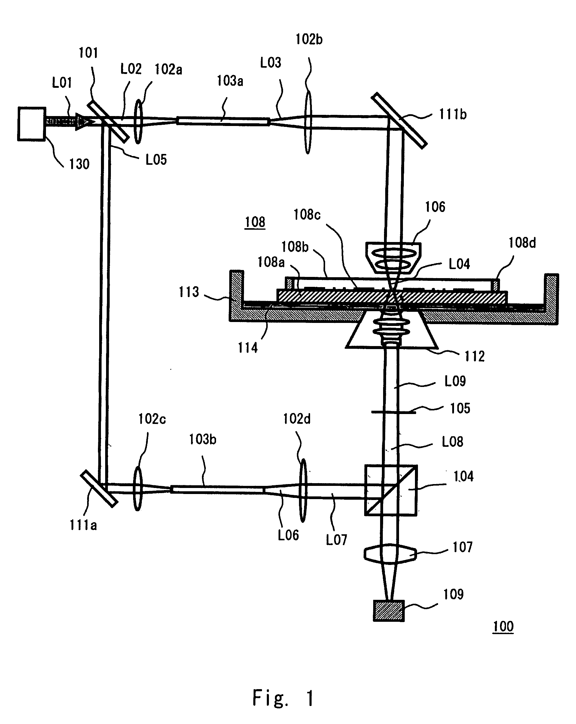
[0076]A photomask inspection apparatus according to embodiment 2 of the present invention will be described with reference to FIG. 2. FIG. 2 shows the configuration of a photomask inspection apparatus 200 according to the present embodiment. As shown in FIG. 2, the photomask inspection apparatus 200 comprises an inspection light source 230, a half mirror 201, lenses 202a to 202d, homogenizing optical systems 203a, 203b, a polarization beam splitter 204, a quarter wavelength plate 205, a condenser lens 206, a projection lens 207, a two-dimensional photosensor 209, mirrors 211a, 211b, an object lens 212, pure water 214, a pure water supply unit 215, and a pure water sucking unit 216. Duplicate description with the embodiment 1 will be omitted.

[0077]The photomask inspection apparatus 200 according to the present embodiment is also for inspecting a finished mask comprising a frame 208d provided so as to surround a pattern surface 208c formed on a mask substrate 208a and a pellicle 208b ...

embodiment 3

[0084]A photomask inspection apparatus according to embodiment 3 of the present invention will be described with reference to FIG. 3. FIG. 3 shows the configuration of part of a photomask inspection apparatus 300 according to the present embodiment. The present embodiment differs from the embodiment 1 in the liquid immersion part of the photomask inspection apparatus. In FIG. 3, the optical basic configuration is omitted because of being the same as in the embodiment 1 shown in FIG. 1. FIG. 3 shows the configuration of the liquid immersion part of the photomask inspection apparatus 300.

[0085]As in the embodiment 1, the photomask inspection apparatus 300 according to the present embodiment is also for inspecting a finished mask comprising a frame 301d provided so as to surround a pattern surface 301c formed on a mask substrate 301a and a pellicle 301b applied to this.

[0086]In the present embodiment, the liquid immersion part is configured such that pure water 305 is in contact with t...


PUM


Abstract

According to one aspect of the present invention, there is provided a photomask inspection apparatus which observes a pattern provided on a mask substrate of a mask to inspect the mask including an object lens, and a liquid that is present between a last lens in the side closer to the mask of the object lens and the mask.

Description

BACKGROUND OF THE INVENTION[0001]1. Field of the Invention[0002]The present invention relates to a photomask inspection apparatus for inspecting photomasks (or also called reticles but herein simply called masks) used in a semiconductor manufacturing process.[0003]2. Description of Related Art[0004]Generally, there are widely known two mask defect inspecting method: an inspection method which compares a mask pattern and design data (generally called a die-to-database comparing method) and an inspection method which compares two mask patterns (generally called a die-to-die comparing method). In either of these inspection methods, an image of a mask pattern is detected with a microscope. At this time, if an optical microscope is used, the mask pattern needs to be illuminated with light. For the light source (i.e., a mask inspection light source), there are two main categories: the use of a lamp and the use of a laser. In photomask inspection apparatuses using a laser, a continuous las...

Claims


Application Information

Patent Timeline
Patent Type & Authority Applications(United States)
IPC IPC(8): G02B3/12
CPCG03F1/84
Inventor TAKEHISA, KIWAMUKUSUNOSE, HARUHIKOAWAMURA, NAOKI
Owner LASERTEC CORP
Why Eureka
Try Eureka