Heating system and method for microfluidic and micromechanical applications

Inactive Publication Date: 2009-07-02
STMICROELECTRONICS SRL
View PDF5 Cites 29 Cited by
  • Summary
  • Abstract
  • Description
  • Claims
  • Application Information

AI Technical Summary

Benefits of technology

[0010]A plurality of heating elements are positioned at different locations adjacent the chamber which contains the fluid. A first heating element is positioned near a bottom surface of the

Problems solved by technology

Often, only very small amounts of fluid are used, either because of a small sample or the expense of the fluid.
Accordingly, manufacturing large qu

Method used


Image

  • Heating system and method for microfluidic and micromechanical applications
  • Heating system and method for microfluidic and micromechanical applications
  • Heating system and method for microfluidic and micromechanical applications

Examples


Example

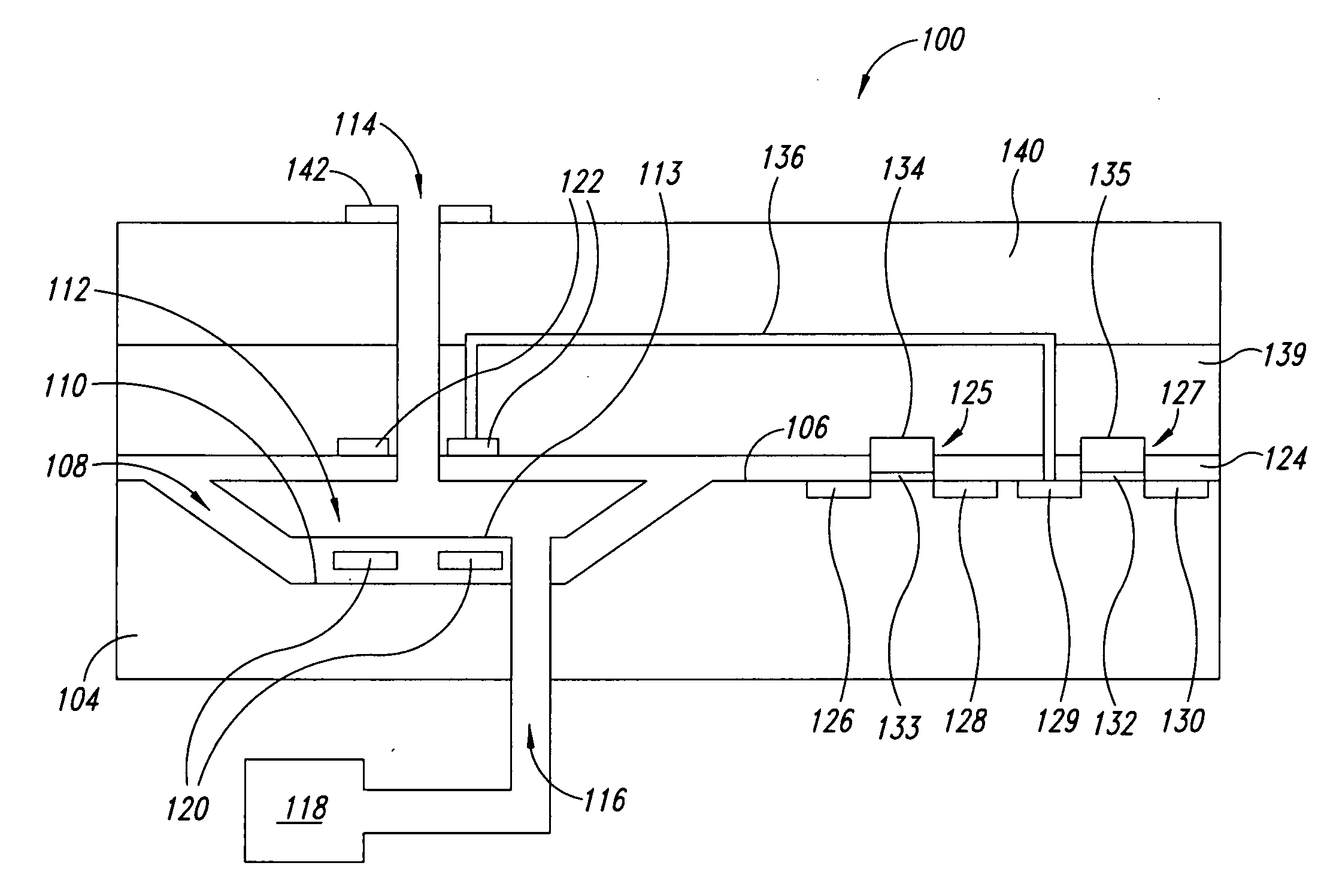
[0019]The following discussion describes various embodiments of an integrated heating assembly 100, followed by a description of an embodiment of fabrication of the same. An integrated semiconductor heating assembly 100 is formed on a substrate 104.

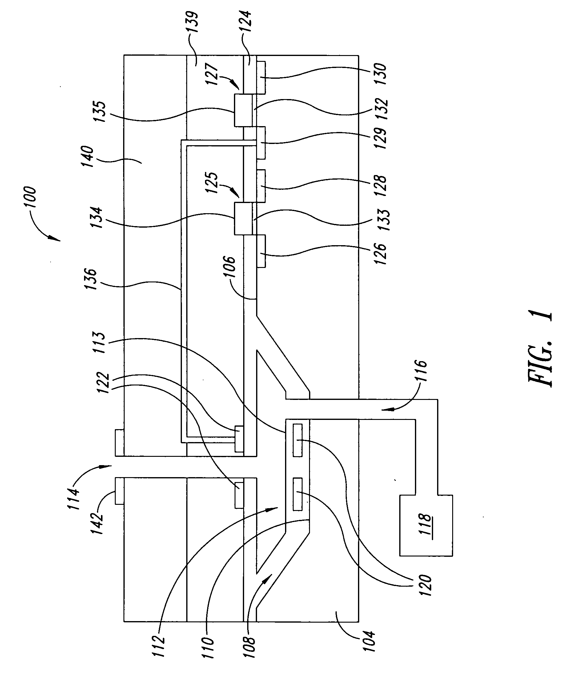
[0020]As shown in FIG. 1, the substrate 104 is monocrystalline semiconductor material, for example silicon. The substrate 104 includes an upper surface 106 and a recess 108 having a lower surface 110. Spaced from the lower surface 110, the integrated heating assembly 100 includes a chamber 112 having a lower surface 113. The chamber 112 is in fluid communication with an exit port 114 for allowing fluid communication between the chamber 112 and a surrounding environment. The chamber 112 is also in fluid communication with an inlet manifold 116, which is configured to introduce a fluid to the chamber 112 from a fluid source 118, externally located with respect to the integrated heating assembly 100.

[0021]The integrated heating assembly 100 ...


PUM

PropertyMeasurementUnit
Temperatureaaaaaaaaaa
Timeaaaaaaaaaa
Electrical resistanceaaaaaaaaaa

Abstract

An integrated semiconductor heating assembly includes a semiconductor substrate, a chamber formed therein, and an exit port in fluid communication with the chamber, allowing fluid to exit the chamber in response to heating the chamber. The integrated heating assembly includes a first heating element adjacent the chamber, which can generate heat above a selected threshold and bias fluid in the chamber toward the exit port. A second heating element is positioned adjacent the exit port to generate heat above a selected threshold, facilitating movement of the fluid through the exit port away from the chamber. Addition of the second heating element reduces the amount of heat emitted per heating element and minimizes thickness of a heat absorption material toward an open end of the exit port. Since such material is expensive, this reduces the manufacturing cost and retail price of the assembly while improving efficiency and longevity thereof.

Description

BACKGROUND[0001]1. Technical Field[0002]The present disclosure relates to microchip heaters for microfluidic and micromechanical applications, and more particularly, to a multi layered heating element structure.[0003]2. Description of the Related Art[0004]Some fluids are processed at temperatures that need to be accurately regulated.[0005]DNA amplification process (PCR, i.e., Polymerase Chain Reaction process) is one process in which accurate temperature control, including repeated specific thermal cycles, needs to be carried out, while avoiding thermal gradients in the fluid. Often, only very small amounts of fluid are used, either because of a small sample or the expense of the fluid. Microchip heaters are particularly suited for this application.[0006]Other examples of fluid processing needing specific thermal characteristics include the implementation of chemical and / or pharmacological analyses, and biological examinations. Other situations that require an accurate, miniaturized...

Claims


Application Information

Patent Timeline
IPC IPC(8): F24H1/10H01L21/02
CPCB41J2/1628B41J2/1629B41J2/16B41J2/14056B41J2/1639B41J2/14137Y10T29/41Y10T29/49401B41J2/1601B41J2/14072Y10T29/49826H01L28/20B81B1/006B81B2201/052B81B2201/058B81C1/00119B81C2201/013B81C2203/075
Inventor FANG, MINGWANG, FUCHAO
Owner STMICROELECTRONICS SRL
Why Eureka
Try Eureka