Integrated shipping fixture and assembly method for jointed wind turbine blades

a wind turbine blade and integrated technology, applied in the field of shipping fixtures, can solve the problems of limiting the maneuverability of trucks, affecting the routing of trucks, and affecting the operation of wind turbines with parallel air flow, etc., and achieve the effect of convenient assembly

Active Publication Date: 2009-07-02
GENERAL ELECTRIC CO
View PDF10 Cites 67 Cited by
  • Summary
  • Abstract
  • Description
  • Claims
  • Application Information

AI Technical Summary

Benefits of technology

[0006]Accordingly, there is a need to provide a shipping fixture that will provide for transport ...

Problems solved by technology

The large blade size may severally limit the maneuverability of the trucks.
Road transport of rotor blades of 50 meters is also very costly.
Furthermore, routing of the trucks may be limited since it may be impossible to ...

Method used


Image

  • Integrated shipping fixture and assembly method for jointed wind turbine blades
  • Integrated shipping fixture and assembly method for jointed wind turbine blades
  • Integrated shipping fixture and assembly method for jointed wind turbine blades

Examples


second embodiment

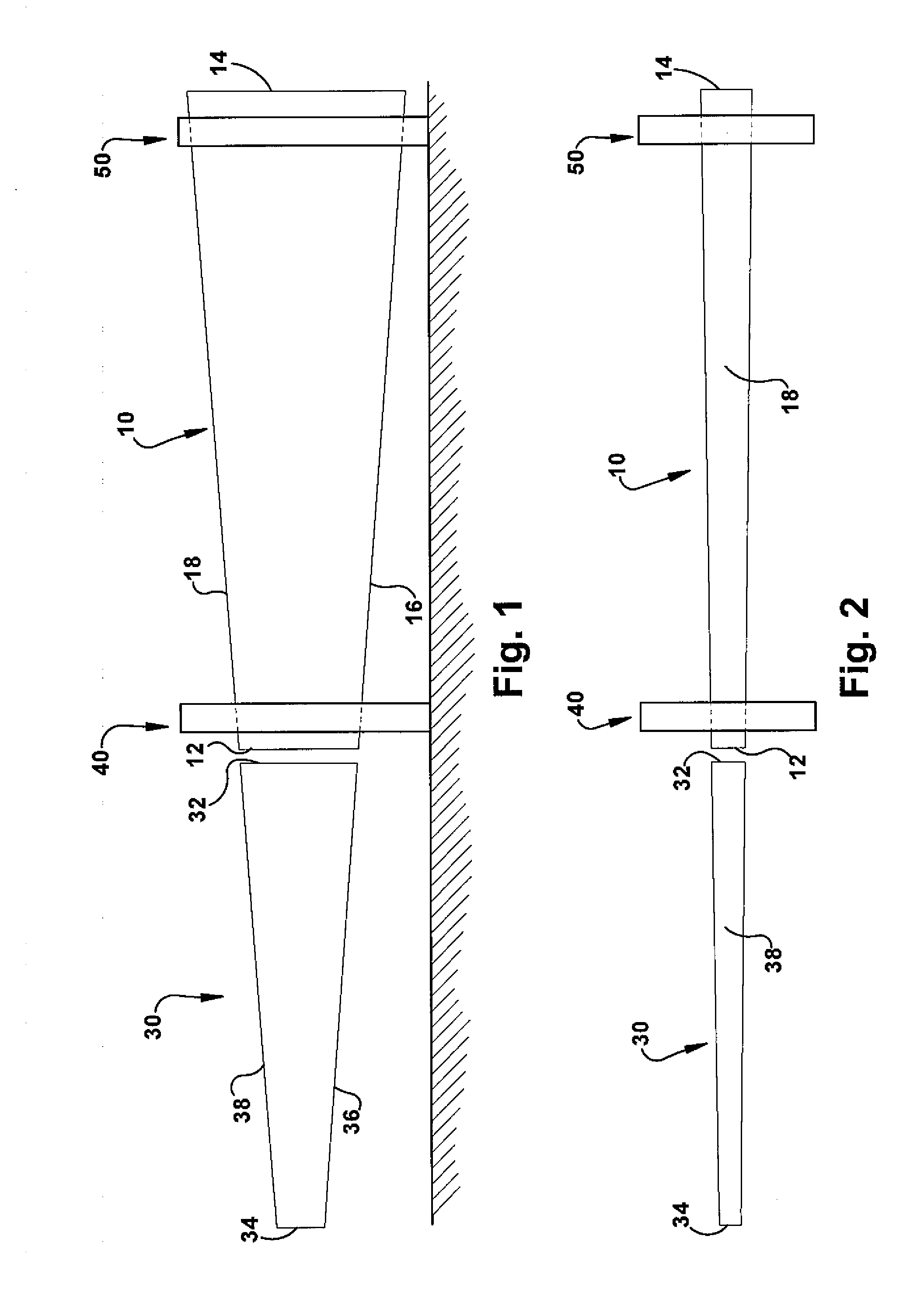
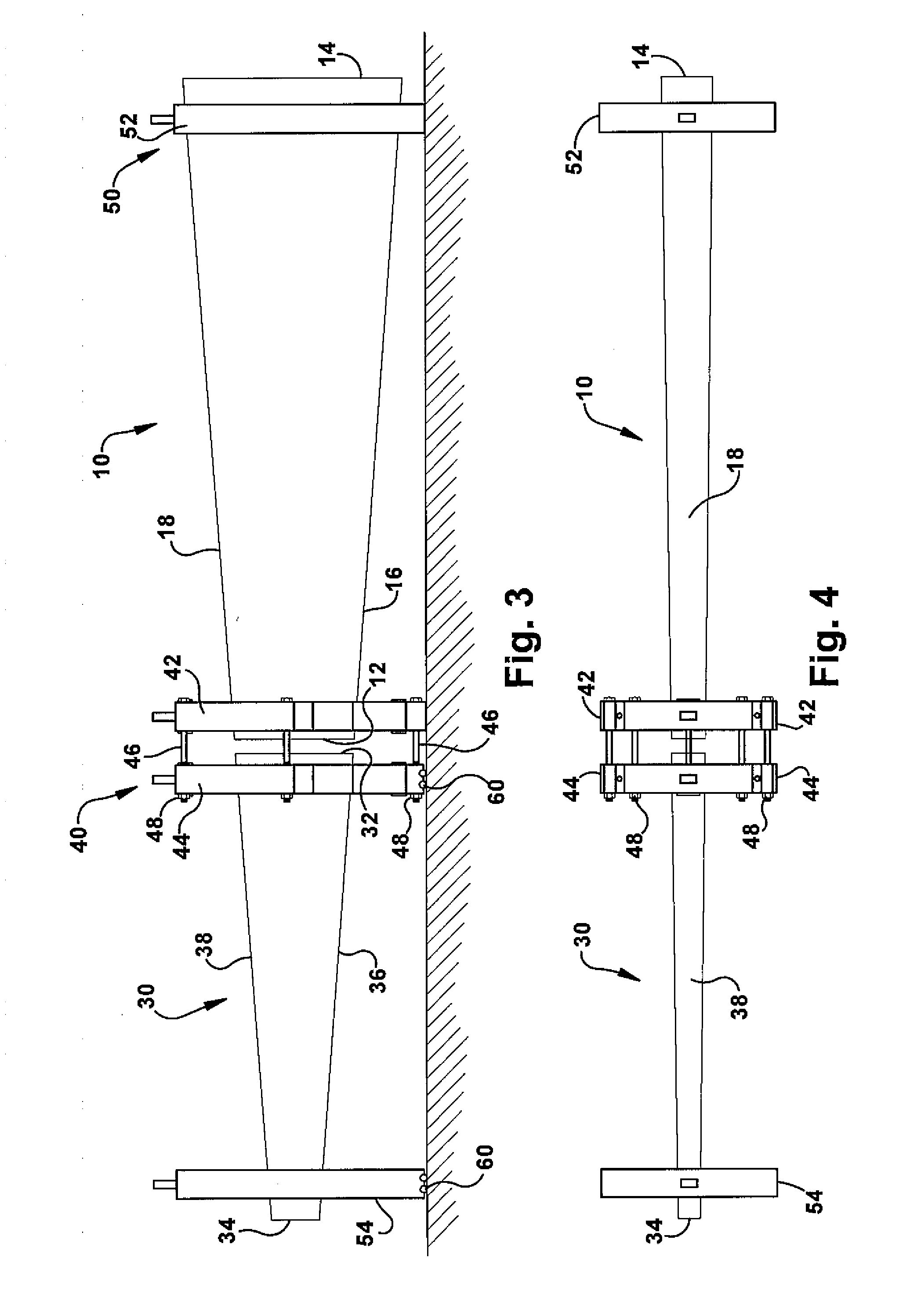
[0039]FIGS. 5A-5B illustrate a representation of the inventive shipping fixture for shipping and assembling a multi-section wind turbine blade with a root section, a mid section and a tip section. The multi-section wind turbine blade includes root section 10, mid-section 20 and tip section 30.

[0040]FIG. 5A illustrates a side-view of a root section 10 mounted on a first shipping fixture 40 and a second shipping fixture 50. The separate mid section 20 section is shown oriented with its connecting end 22 adjacent to the connecting end 12 of root section 10 and opposing end 24 facing away from the root 10. The separate tip section 30 is shown oriented with connecting end 32 facing the mid section 20. The first shipping fixture 40 supports the connecting end 12 of the root section 10. The second shipping fixture 50 supports the opposing end 14 of the root section 12. The larger and heavier leading edge 16 for the root section 10 may be mounted on the underside of the shipping fixtures, w...

first embodiment

[0045]FIG. 7B illustrates the wind turbine blade sections arranged for alignment and clamping according to the side-by-arrangement. The cradle 241 of the first shipping fixture 240 has been expanded into a first support section 240A for supporting the connecting end 215 of blade root section 210 and a second support section 240B for supporting the connecting end 235 of blade tip section 230, in a manner as previously described in detail with respect to FIGS. 6A-6D. The third shipping fixture 270 has been expanded to separate out a fully detachable cradle unit 272 to support the tip end 236 of blade tip section 230. The individual cradle units provide support and alignment for the root section 210 and the tip section 230 during clamping.

[0046]A second embodiment of the side-by-side arrangement for a shipping fixture for wind turbine blades is illustrated in FIG. 8. A first fixture 340, a second fixture 350 and a third fixture 370 are provided. The first shipping fixture 340 and the s...


PUM


Abstract

An integrated shipping and alignment fixture for shipping and aligning a jointed multi-section wind turbine blade is provided. The fixture includes a first shipping fixture supporting a first end of a section of the multi-section wind turbine blade; a second shipping fixture supporting a second end of a section of the multi-section wind turbine blade; supports on the the first shipping fixture and the second shipping fixture for retaining one end of the section of the wind turbine blade; an aligning device for aligning a detached section of the multi-section wind turbine blade with a retained section of the wind turbine blade; and a clamping device for clamping a detached section with a retained section.

Description

RELATED APPLICATIONS[0001]This application is related to a General Electric Company application Ser. No. 11,380,936 by Enno Eyb, filed on Apr. 30, 2006 and entitled “MODULAR ROTOR BLADE FOR A WIND TURBINE AND METHOD FOR ASSEMBLING SAME”.BACKGROUND OF THE INVENTION[0002]The invention relates generally to shipping fixtures and more specifically to a shipping fixture for jointed multi-section wind turbine blades that provides for assembly of the blade sections at the wind turbine site.[0003]In recent years, wind turbines have become increasingly important in power generation. With increased environmental concerns related to fossil fuel power generation, wind power will grow in importance in the mix of providing electrical power. Consequently, more wind turbines will be installed. For economic reasons, it is desirable to increase the installed power per turbine. As the installed power is proportional to the diameter of the turbine rotor, the rotor sizes and turbine sizes become larger. ...

Claims


Application Information

Patent Timeline
IPC IPC(8): B65D85/68
CPCF03D1/005Y02E10/721F05B2240/302F03D1/0675F03D13/40Y02E10/72
Inventor LIVINGSTON, JAMIE T.
Owner GENERAL ELECTRIC CO
Why Eureka
Try Eureka