Shift control apparatus for automatic transmission

a technology of automatic transmission and control apparatus, which is applied in mechanical apparatus, instruments, digital data processing details, etc., can solve the problems of poor controllability of high clutch, large shock effect, engine racing, etc., and achieve the effect of eliminating torque fluctuation and quick shifting

Active Publication Date: 2009-07-02
AISIN AW CO LTD
View PDF2 Cites 28 Cited by
  • Summary
  • Abstract
  • Description
  • Claims
  • Application Information

AI Technical Summary

Benefits of technology

[0009]Aspects of the present invention provide a shift control apparatus for an automatic transmission that is structured so as to perform the shifting quickly and also to eliminate the torque fluctuation at the intermediate shift speed during downshift to a speed spaced apart by two or more steps through the intermediate shift speed by disconnecting and connecting the respective pairs of the friction engagement elements, through forming a low shift speed by engaging a first shift engagement element after releasing a first and second shift release elements and also by engaging a second shift engagement element while controlling the torque capacity of the second shift release element by feedback control.

Problems solved by technology

As a result, the high clutch does not automatically slip during the 4th-to-3rd shift, resulting in a poor controllability of the high clutch.
In addition, because the gear ratio changes quickly during the 6th-to-4th shift and the change in gear ratio is suppressed in the narrow range of the 4th-to-3rd shift, it is possible that the engine will race due to difficulty in control.
Moreover, the clutch distribution ratios of the high clutch on the release side and a 3-5 reverse clutch (C-3) on the engagement side are small during the 6th-to-4th shift, which has a large effect on shock, and causes a susceptibility to variation of hydraulic pressure.
During shifting by the engagement switching of the pairs of friction engagement elements (engagement switching of four elements), because the shift control apparatus described in JP-A-2003-106440 performs control such as engaging a friction engagement element (clutch 3-5R / C) serving as a shift engagement element at the end of a first changeover (first shift) in which friction engagement elements (brake 2-6 / B and clutch H / C) serving as shift release elements are released, there is a concern that an occurrence of torque fluctuation at the intermediate shift speed can generate an uncomfortable shift shock, and also a concern that a slowing of rev-up of a turbine rotation in that period can cause a longer time required until the end of a second changeover (second shift), resulting in a longer time for shifting.

Method used


Image

  • Shift control apparatus for automatic transmission
  • Shift control apparatus for automatic transmission
  • Shift control apparatus for automatic transmission

Examples


Embodiment Construction

[0029]Exemplary embodiments of the present invention will be described below with reference to FIGS. 1 to 13.

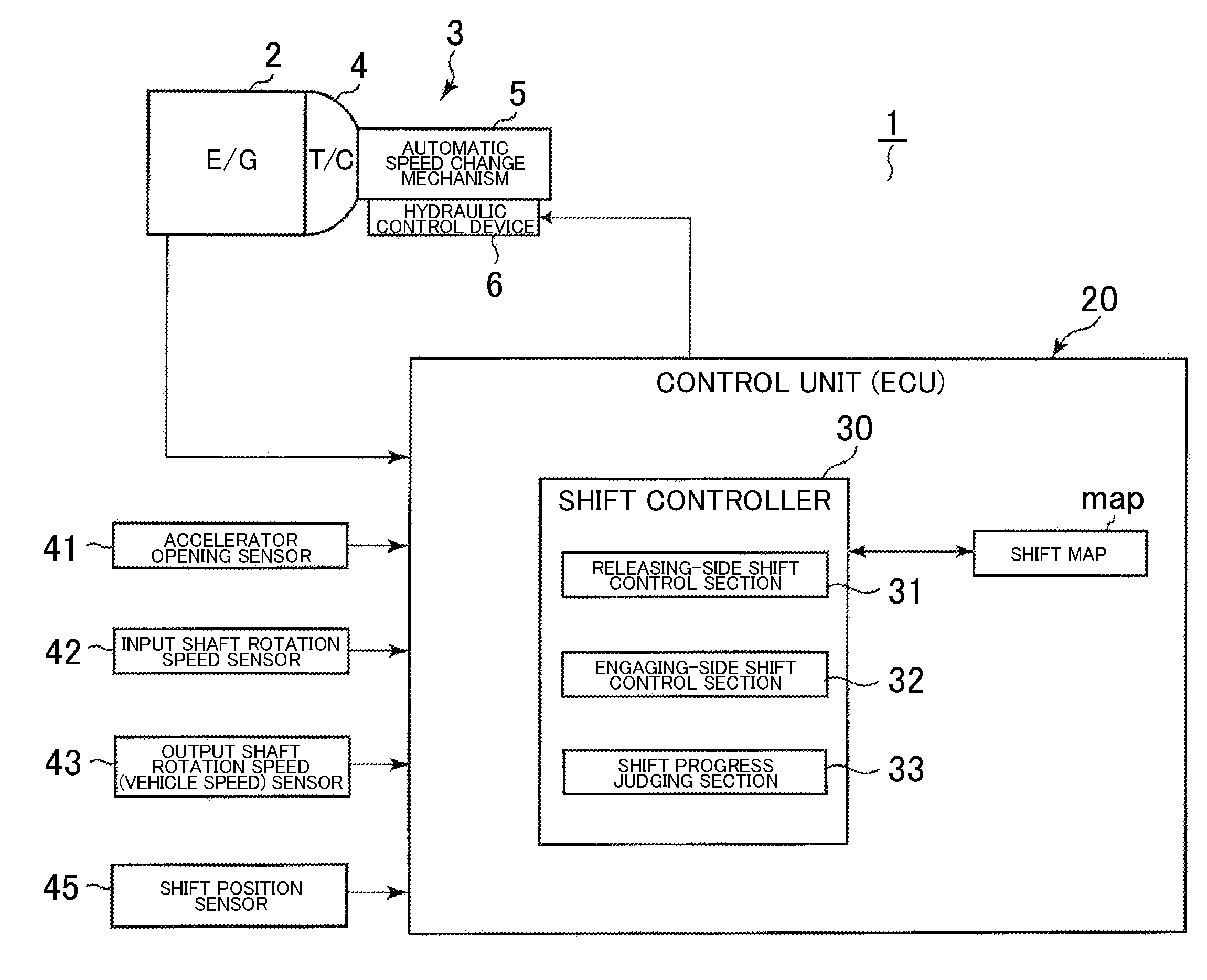
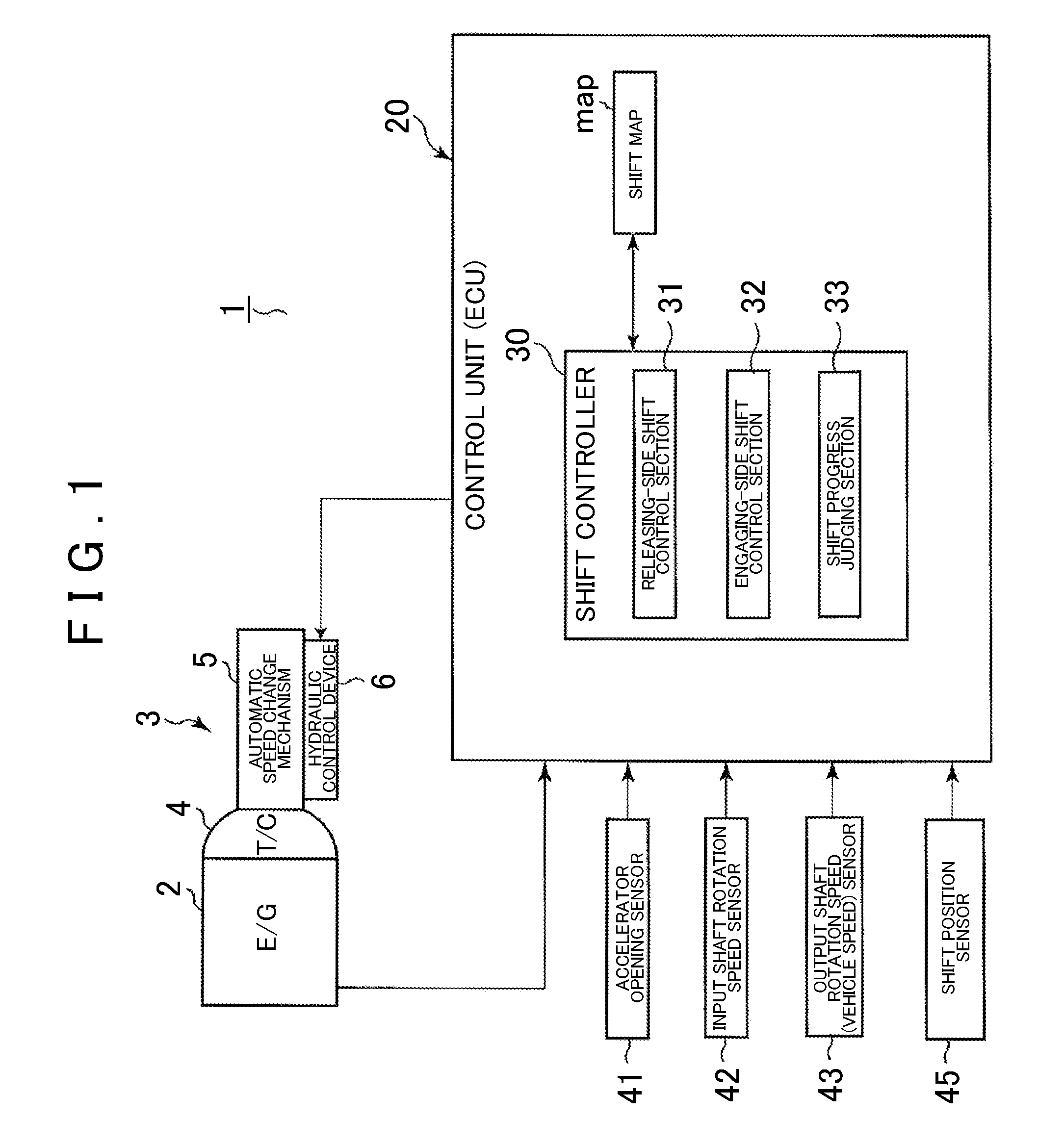
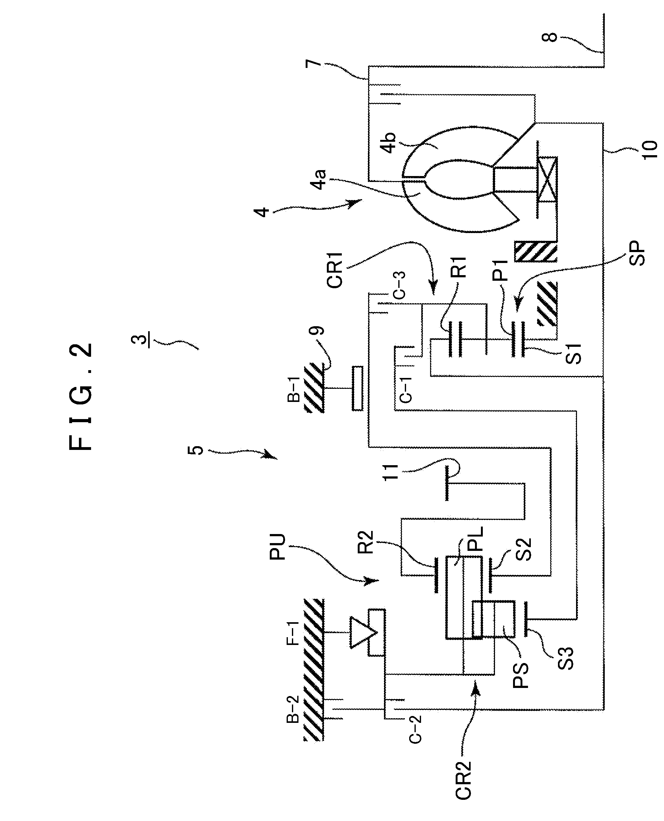
[0030]First, the outline structure of an automatic transmission 3 to which the present invention can be applied will be described with reference to FIG. 2. As shown in FIG. 2, the automatic transmission 3, which is suitable for use in, for example, an FF (front engine, front drive) type vehicle, has an input shaft 8 of the automatic transmission 3 connectable to an engine 2 (refer to FIG. 1), and is provided with a torque converter 4 and an automatic speed change mechanism 5 with their centers on the axis of the input shaft 8. Note that a reference numeral 9 shows a transmission case for housing the automatic speed change mechanism 5.

[0031]The automatic transmission 3 is a stepped automatic transmission, which has clutches C-1, C-2, and C-3, and brakes B-1 and B-2 serving as friction engagement elements whose engagement states achieve a plurality of corresponding power transm...


PUM


Abstract

A shift controller controls a downshift to a low shift speed, spaced apart from a high shift speed by two or more steps, through an intermediate shift speed, by first releasing first and second shift release elements, then engaging a first shift engagement element, and finally engaging a second shift engagement element, while controlling the torque capacity of the second shift release element by feedback control. As a result of releasing the first and second shift release elements before engaging the first shift engagement element, it is possible to rev up an input rotation at maximum performance of an engine to reduce the time for shifting. As a result of the feedback control of the torque capacity of the second shift release element after engaging the first shift engagement element, a torque fluctuation at the intermediate shift speed can be reduced to avoid occurrence of an uncomfortable shift shock.

Description

CROSS-REFERENCE TO RELATED APPLICATIONS[0001]This application claims priority from Japanese Patent Application No. 2003-106440 filed on Sep. 9, 2001, the disclosure of which, including the specification, drawings and abstract, is incorporated herein by reference in its entirety.BACKGROUND[0002]1. Technical Field[0003]Aspects of the present invention relate to a shift control apparatus for an automatic transmission mounted on a vehicle such as an automobile, and more in detail, to a shift control apparatus for an automatic transmission that is capable of providing improvement in a shift shock during a jumping shift by so-called clutch-to-clutch operation (engagement switching).[0004]2. Description of the Related Art[0005]Conventionally, for example, a stepped automatic transmission mounted on a vehicle is capable of shifting speeds by controlling the engagement state of a plurality of friction engagement elements (clutches and brakes) using a hydraulic control device, and thus formin...

Claims


Application Information

Patent Timeline
Patent Type & Authority Applications(United States)
IPC IPC(8): B60W10/10G06F17/00F16H59/68F16H61/08F16H61/68F16H61/684F16H61/686
CPCF16H61/061F16H61/686F16H2306/52F16H2306/14F16H2306/44F16H2061/0444
Inventor SATO, HARUKIIWAI, NOBUHIROARAKI, SHOICHIROTSUTSUI, HIROSHI
Owner AISIN AW CO LTD
Why Eureka
Try Eureka