Method for Determining Receiver Orientations

a receiver orientation and receiver technology, applied in the field of geophysical prospecting, can solve the problems of low receiver azimuth accuracy provided by this method, the reliability of the present direct measurement system of marine csem receivers, and the significant effect of decomposition components

Inactive Publication Date: 2009-07-02
EXXONMOBIL UPSTREAM RES CO
View PDF10 Cites 16 Cited by
  • Summary
  • Abstract
  • Description
  • Claims
  • Application Information

AI Technical Summary

Problems solved by technology

Effects on the decomposed components could be significant when the receiver cannot be oriented to those preferred directions because of inaccurate receiver orientations.
Present direct measurement systems for marine CSEM receivers have reliability problems.
Receiver azimuth accuracy provided by this method is not very high.
It could be worse for a ship without a dynamic positioning system in rough weather, conditions.
All three of these methods, though widely used, address only the receiver azimuth, but do not disclose how to determine receiver orientations uniquely, i.e. both the azimuth and the tilts of the two horizontal channels.
(2) The vertical electric component is either not measured or is not fully utilized in data interpretation.
(3) No reliable and accurate method is available to determine the receiver orientations.
In addition to the three reasons detailed above, the extent of possible impact on CSEM results of even small receiver tilt angles may not be appreciated.

Method used


Image

  • Method for Determining Receiver Orientations
  • Method for Determining Receiver Orientations
  • Method for Determining Receiver Orientations

Examples


example

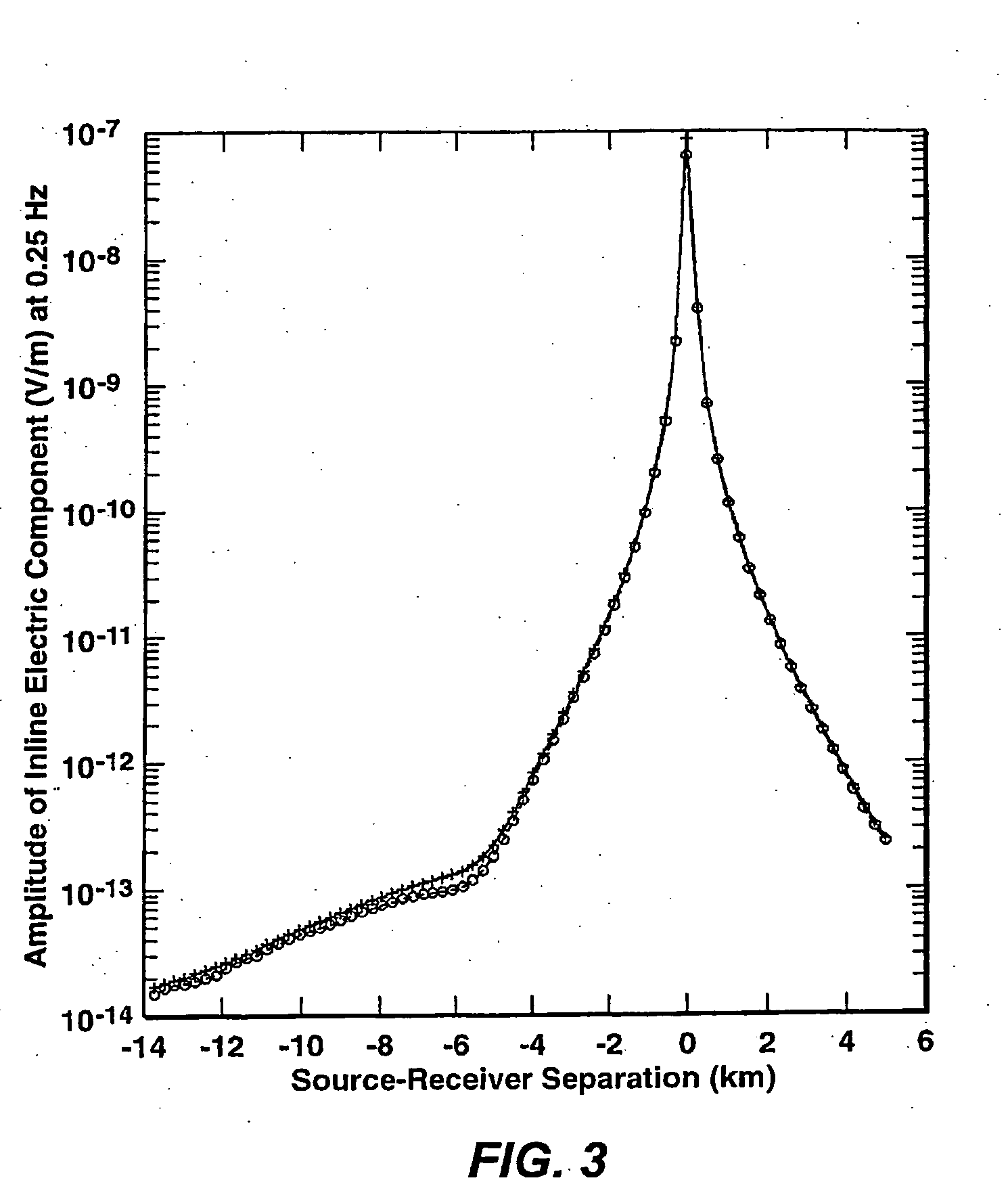
[0033]A 1D model with the same source and receiver geometry as the example of FIGS. 3-5 was used to generate a synthetic data set at frequencies of 0.125, 0.25, 0.5, 1.25, and 2.0 Hz for a receiver with (α, β, γ)=(330.0, 2.0, 4.0). This data set was then used to test how well the present inventive method could determine the receiver orientations. In this example, the inversion process was set up for simultaneously determining the receiver orientations and resistivity model. The initial resistivity model consisted of air, seawater and a uniform half-space for the sedimentary seafloor and the initial angles for receiver were (300.0, 0.0, 0.0). After applying the present inventive method, the resulting orientation angles were (α, β, γ)=(329.97, 1.95, 3.88). The recovered angles are very close to the angles used to generate the synthetic data, demonstrating the accuracy of the inventive method.


PUM


Abstract

Method for completely specifying orientation of electromagnetic receivers dropped to the ocean bottom in an electromagnetic survey. Survey data are selected, rejecting noisy data with long offsets and data where the receiver has saturated with short offsets (61). A model is developed comprising three independent receiver orientation angles completely specifying the receiver orientation in three dimensions, and an earth resistivity model including a water layer and possibly an air layer (62). Maxwell's equations, applied to the model and the selected data, are then inverted to determine the receiver orientations (63).

Description

[0001]This application claims the benefit of U.S. Provisional Application No. 60 / 701,817 filed on Jul. 22, 2005.FIELD OF THE INVENTION[0002]This invention relates generally to the field of geophysical prospecting including reservoir delineation and, more particularly, to controlled-source electromagnetic surveying for geophysical applications. Specifically, the invention is a method for determining electromagnetic receiver orientations.BACKGROUND OF THE INVENTION[0003]The marine controlled-source electromagnetic (“CSEM”) exploration method uses man-made sources to generate electromagnetic (EM) waves and deploys receivers on the seafloor to record electromagnetic signals. The recorded electromagnetic signals are analyzed to infer subsea floor structures and / or determine nature of particular structures such as reservoirs. FIG. 1 illustrates a typical deployment of CSEM equipment, with an horizontal electric dipole (HED) source 11 towed by a vessel above the water bottom 12 on which re...

Claims


Application Information

Patent Timeline
Patent Type & Authority Applications(United States)
IPC IPC(8): G06F19/00G01V3/00
CPCG01V3/12G01V3/083Y02A90/30
Inventor LU, XINYOU
Owner EXXONMOBIL UPSTREAM RES CO
Why Eureka
Try Eureka