Shaver

Inactive Publication Date: 2009-07-09
MATSUSHITA ELECTRIC WORKS LTD
View PDF19 Cites 15 Cited by
  • Summary
  • Abstract
  • Description
  • Claims
  • Application Information

AI Technical Summary

Benefits of technology

[0008]It is an object of the present invention to provide a shaver of which blade edge can readily be kept clean.
[0009]The shaver of the present invention comprises a fuel cell which supplies power to a driving part for driving and displacing a blade, and a heat transfer part for guiding heat from the above described fuel cell to the vicinity of the blade. Since a shaver of the configuration described above comprises a

Problems solved by technology

However, water drops may remain in the interior after the water w

Method used


Image

  • Shaver
  • Shaver
  • Shaver

Examples


embodiment 1

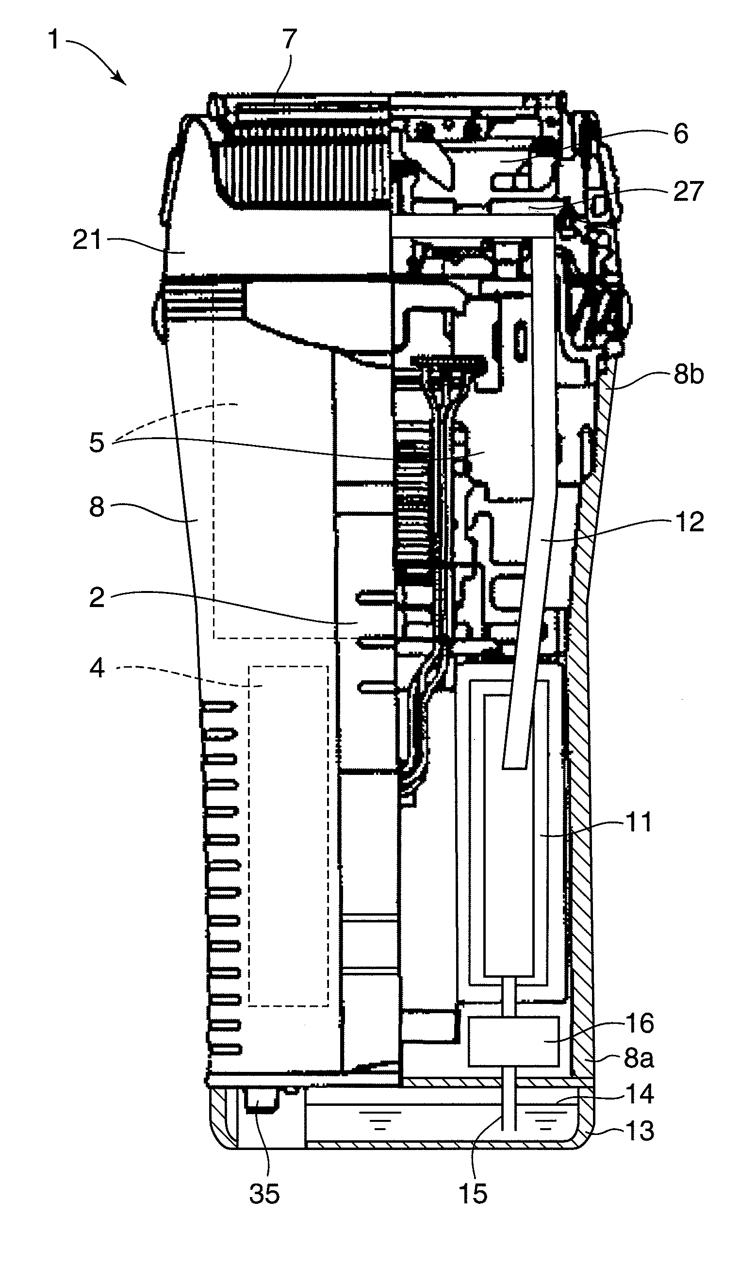
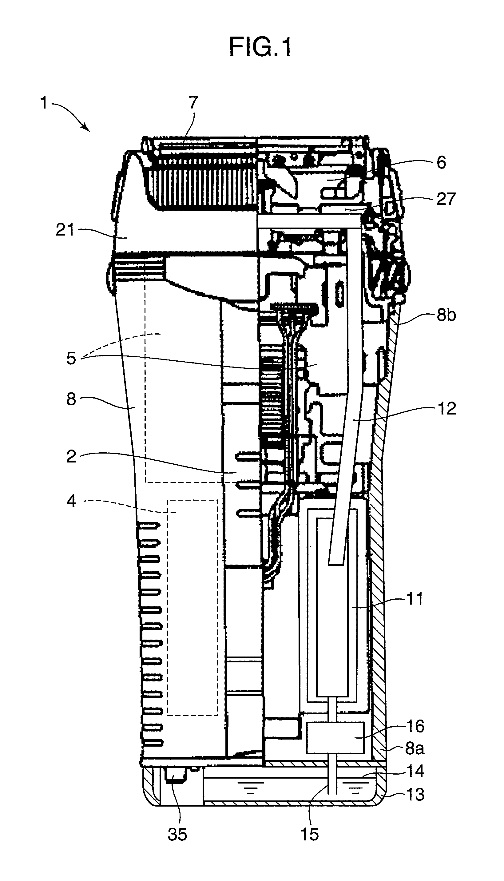
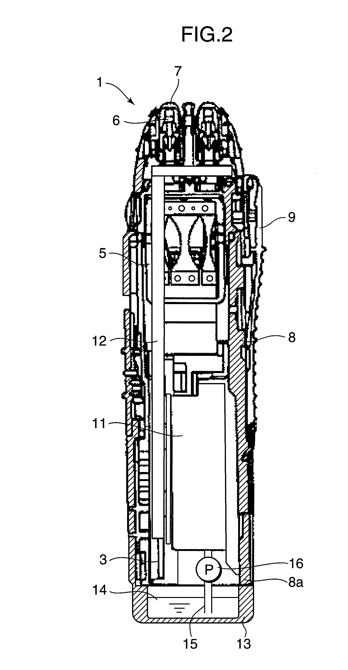
[0018]FIGS. 1 and 2 illustrate the configuration of a shaver 1 relating to an embodiment of the present invention. FIG. 1 is a partially cut-off front view and FIG. 2 is a sectional view in a longitudinal direction.

[0019]In the shaver 1 in FIGS. 1 and 2, when a slide switch 2 is actuated, an electric circuit formed on a substrate 3 provides electric power stored in a secondary cell 4 to a motor 5 to cause an inner blade 6 to make a linear reciprocating motion so that a hair removal operation is performed between the aforementioned inner blade 6 and an outer blade 7. Further, a trimmer 9 provided in the back face of a body 8 is actuated, as desired, so that the driving force is transferred to the trimmer 9 as well, enabling hair removal operation.

[0020]It should be noted that in the shaver 1, while the electric power generated by a fuel cell 11 is used for electrically energizing the motor 5 which is a driving part, waste heat from the fuel cell 11 is guided to the vicinity of the ab...

embodiment 2

[0032]FIGS. 6 and 7 illustrate the structure of a shaver 41 relating to another embodiment of the present invention. FIG. 6 is a partially cut-off front view, and FIG. 7 is a sectional view in a longitudinal direction. This shaver 41 is similar to the above described shaver 1, and corresponding parts are given like symbols, thereby omitting the description thereof.

[0033]In FIGS. 6 and 7, it should be noted that in this shaver 41, a blower 42 is used as a heat transfer part for conducting heat such as waste heat from the above described fuel cell 11 to the rubber pressing plate 27, and that the blower 42 has both the functions of a blower for heating the blades 6 and 7 and a blower for releasing heat in the power generation part of the fuel cell 11. That is, the blower 42 has both an air blowing function for heating the blades 6 and 7 and an air blowing function for releasing heat from the heat generation part of the fuel cell 11.

[0034]For this purpose, an intake port 43 is formed in...


PUM


Abstract

A shaver using a fuel cell as the power supply for a motor to free the shaver from the constraints imposed by power supply wiring, thereby widening the selection range of storage place of shaver. Waste heat produced by power generation of the fuel cell is introduced through a heat pipe to the vicinity of an inner blade, and the fuel cell is also used as the heat source for heating the inner blade. Consequently, without use of a dedicated cleaner, drying of the shaver after it is washed by water can be promoted and the blade and a blade can be sterilized by heat.

Description

TECHNICAL FIELD[0001]The present invention relates to a shaver which is embodied as an electric razor or trimmer, particularly to ones which are preferably implemented in a configuration in which hair and skin tissues adhered to the blade edge can be washed off with water.BACKGROUND ART[0002]A typical conventional art of a water washable shaver as describe above has been proposed, for example, by the present applicant in Patent Document 1. In this conventional art, there is proposed a shaver in which an inner blade is driven at a high speed during shaving and at a low speed during water washing so that water or chipped hair will not be scattered during water washing. However, water drops may remain in the interior after the water washing, resulting in insufficient disinfection and sterilization.[0003]Accordingly, a cleaner has been proposed, for example, in Patent Documents 2 and 3, which is configured such that the blade edge is cleaned with alcohol after use and thereafter is furt...

Claims


Application Information

Patent Timeline
IPC IPC(8): B26B19/38B26B19/28
CPCA45D27/46B26B19/04B26B19/28B26B19/282B26B19/382B26B19/3853Y02B90/18H01M8/04007H01M8/04059H01M8/04216H01M16/006H01M2250/30Y02E60/50B26B19/3873Y02B90/10Y02E60/10B26B19/38B26B19/44
Inventor KITAMURA, HIROYASU
Owner MATSUSHITA ELECTRIC WORKS LTD
Why Eureka
Try Eureka