Automated Tank Cleaning Monitoring System

a monitoring system and automatic technology, applied in the direction of cleaning hollow objects, cleaning processes and utensils, cleaning using liquids, etc., can solve the problems of not adequately cleaning the tank interior, affecting the quality of finished products being processed or manufactured, and unable to achieve the effect of fully cleaning, etc., to achieve the effect of evaluating the cleaning efficacy

Active Publication Date: 2009-07-09
SPRAYING SYST
View PDF9 Cites 17 Cited by
  • Summary
  • Abstract
  • Description
  • Claims
  • Application Information

AI Technical Summary

Benefits of technology

[0009]The invention provides a tank cleaning verification process that works in conjunction with a specialized spray head to evaluate cleaning efficacy and to ensure proper cleaning. The system includes an encoder, and one or more pressure sensors to verify proper operation as the tank cleaning system automatically accounts for one or more characteristics of the vessel being cleaned and modifies the cleaning operation accordingly.

Problems solved by technology

Moreover, paddles, mixers, and other equipment within a tank may trap debris via a coating or other deposit.
Unwanted contaminants in the tank may negatively impact the quality of the finished product being processed or manufactured.
Moreover, the failure to adequately clean the tank interior can violate regulations relevant to certain industries such as pharmaceutical processing.
While this system is simple and mechanically robust, it creates certain inefficiencies and can also be less than fully effective depending upon the mode of operation.
With respect to effectiveness, it will be appreciated that known systems such as those described above are not adapted to provide a constant volume of cleaning solution against all portions of a uniformly soiled surface.
Moreover, systems such as those described above are not adapted to provide a volume of cleaning solution against particular portions of the interior in relation to the known heavy soiling of those portions.
For example, in the case of a deposit ring at a vessel fill line, although the fill line portion of the interior is known to experience increased soiling, existing systems do not allow the operator to customize the clean operation to more heavily clean such portions.
Thus, in typical uses, the systems described above may lead to excess cleaning of some tank portions and inadequate cleaning of other portions.
Although the cleaning duration may be prolonged to ensure adequate cleaning of the most heavily soiled interior portions, this leads to additional waste of time, cleaning fluid, and energy with respect to the lightly soiled surfaces.

Method used


Image

  • Automated Tank Cleaning Monitoring System
  • Automated Tank Cleaning Monitoring System
  • Automated Tank Cleaning Monitoring System

Examples


Embodiment Construction

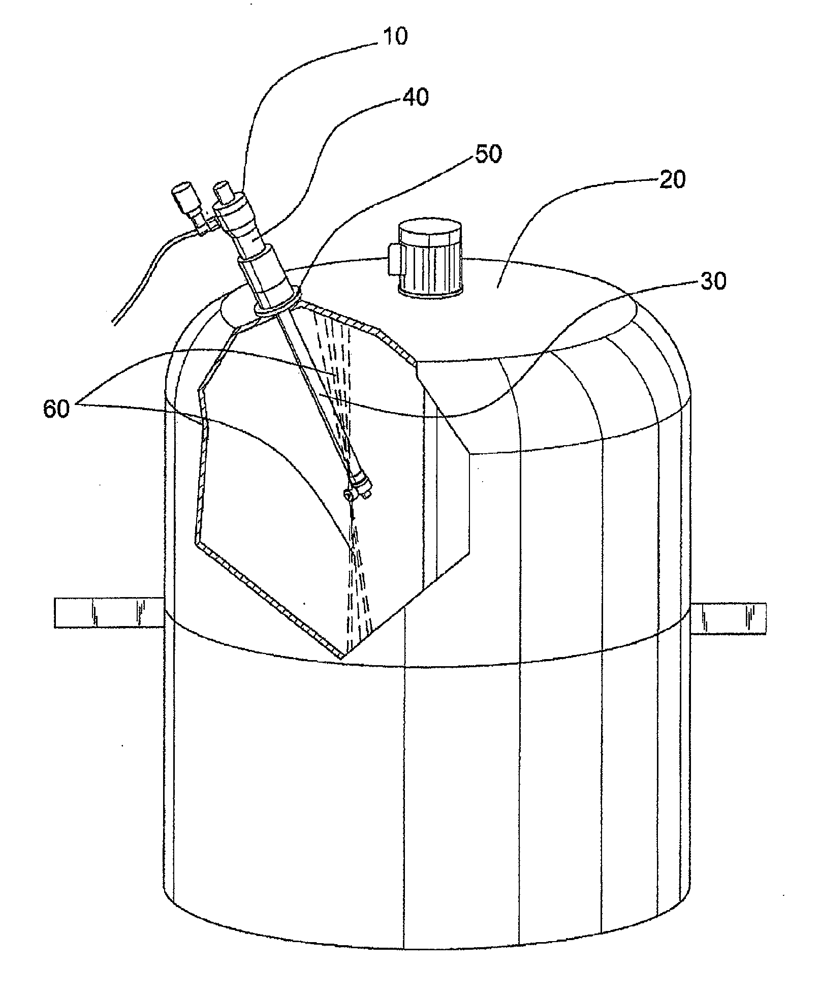
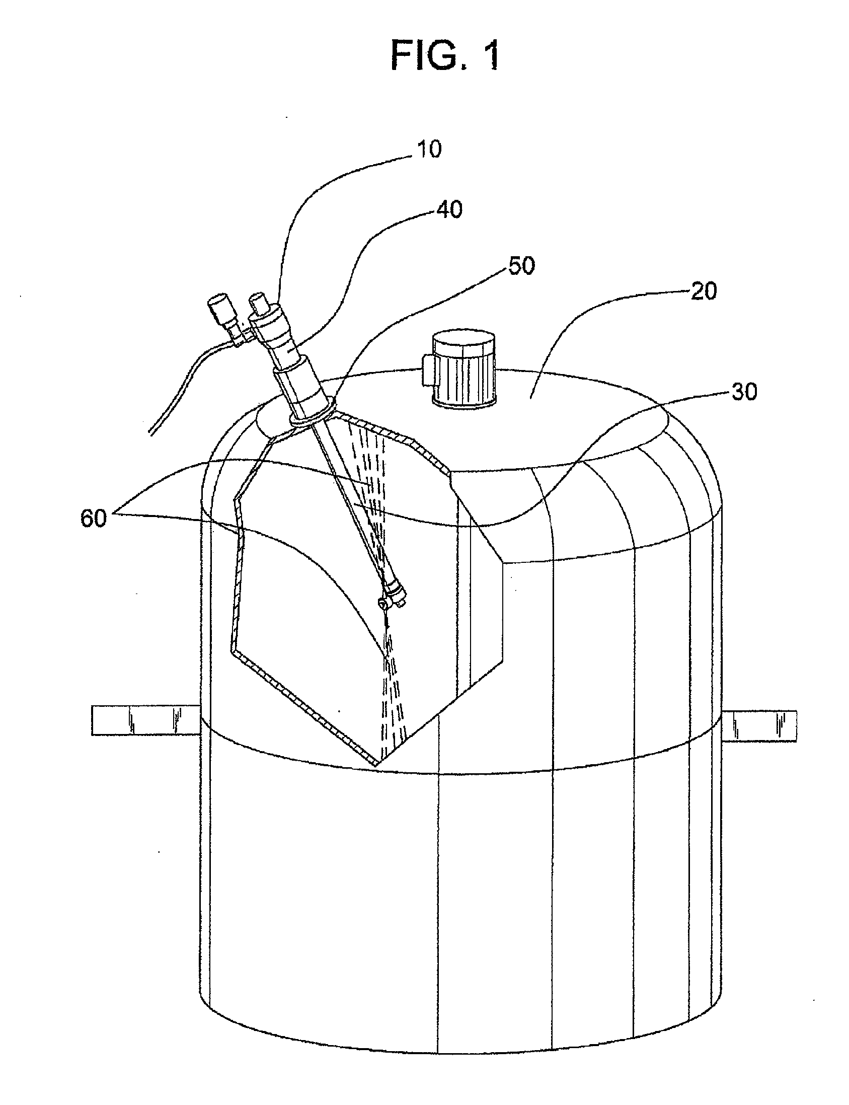
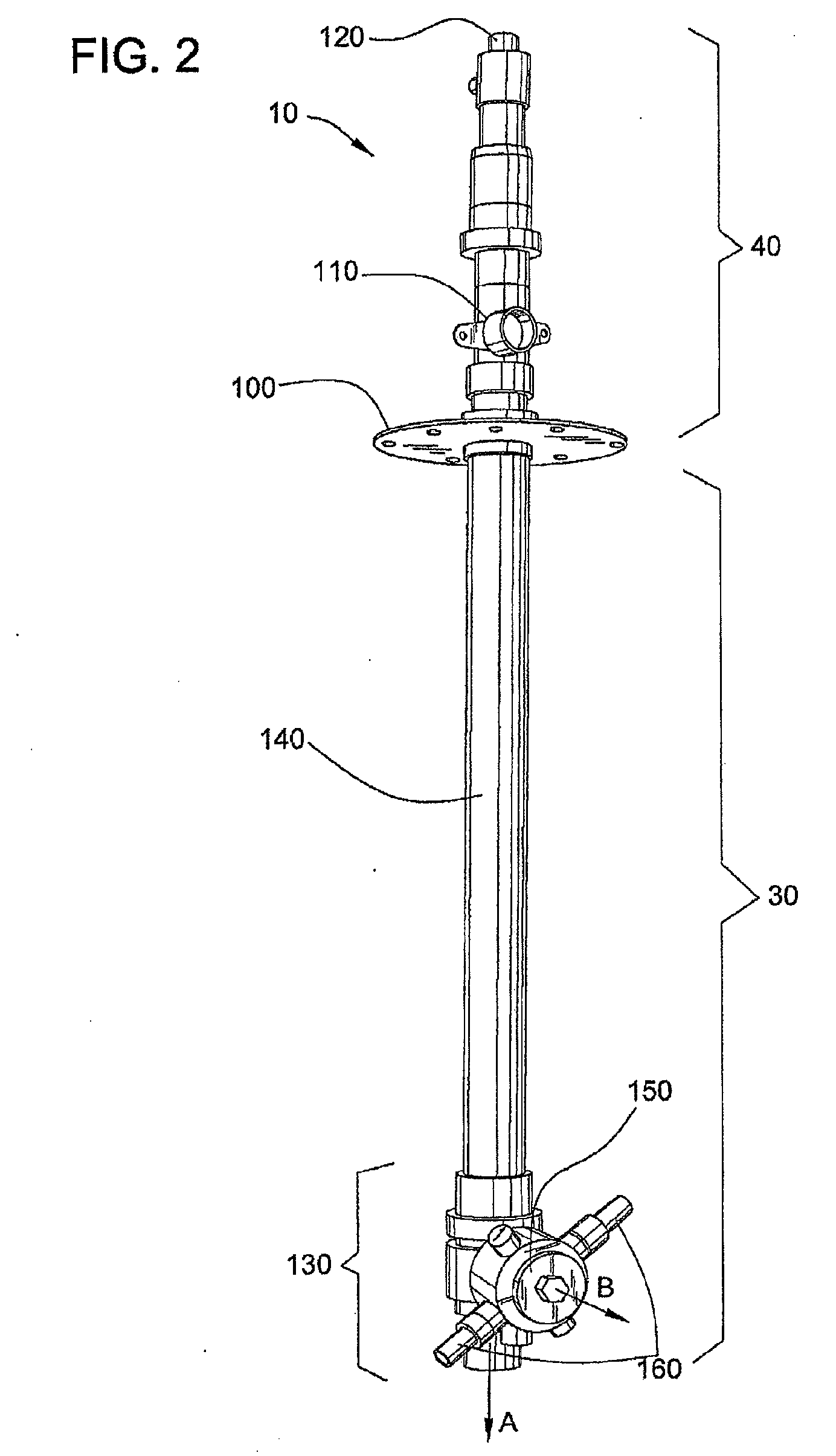
[0019]Referring now more particularly to the drawings, there is shown an illustrative tank cleaning apparatus 10 which has particular utility in selectively cleaning the interior surface of a tank 20. The tank cleaning apparatus 10, which will be discussed in greater detail with reference to FIG. 2, comprises a tubular portion 30 extending into the tank 20 and an actuating portion 40 situated outside of the tank 20.

[0020]While the inner 30 and outer 40 portions of the cleaning apparatus 10 are in mechanical and fluid communication as will be discussed in greater detail hereinafter, the interior volume of the tank 20 is sealed from external environment via an annular seal, e.g. a deformable or compressible flange at the location 50 in the tank 20 at which the inner tubular portion 30 of the cleaning apparatus 10 enters the tank 20.

[0021]During a cleaning process, the tank cleaning apparatus 10 projects a cleaning fluid in one or more streams numbered as 60 against the walls of the ta...


PUM


Abstract

A tank cleaning verification process works in conjunction with a specialized spray head to evaluate cleaning efficacy and to ensure proper cleaning. The system includes an encoder, and one or more pressure sensors to verify proper operation as the tank cleaning system automatically accounts for one or more characteristics of the vessel being cleaned and modifies the cleaning operation accordingly.

Description

CROSS-REFERENCE TO RELATED APPLICATIONS[0001]This patent application is a continuation-in-part of copending U.S. patent application Ser. No. 11 / 612,979, filed Dec. 19, 2006, which is herein incorporated by reference in its entirety for all that it teaches without exclusion of any part thereof, as if fully set forth herein.FIELD OF THE INVENTION[0002]The present invention relates generally to tank cleaning verification and control, and more particularly to internal tank cleaning systems and apparatus which are particularly adapted for cleaning validation.BACKGROUND OF THE INVENTION[0003]Fluid containment tanks are utilized in a multitude of industrial processes such as food and chemical manufacturing and processing, pharmaceutical manufacturing, wine preparation, material fermentation, and so on. It is often critical to ensure that the interior of the tank is free of unwanted debris and contaminants. For example, a tank that is typically filled to a certain level may exhibit a “tub r...

Claims


Application Information

Patent Timeline
Patent Type & Authority Applications(United States)
IPC IPC(8): B08B9/08B08B9/093
CPCB08B9/0936
Inventor BRAMSEN, FRANKLIN ERIK
Owner SPRAYING SYST
Why Eureka
Try Eureka