
Clutch Housing

a technology of clutch housing and housing plate, which is applied in the direction of friction clutch, mechanical actuated clutch, clutch, etc., can solve the problems of affecting the efficiency of power transmission and huge power loss, and achieve the effects of improving the clutch housing structure, high friction coefficient, and improving imperfections

Inactive Publication Date: 2009-07-09
LIN I
View PDF8 Cites 1 Cited by
  • Summary
  • Abstract
  • Description
  • Claims
  • Application Information

AI Technical Summary

Benefits of technology

[0010]The objective of the present invention is to provide an improvement of the clutch housing structure, comprising a housing that fits the clutch carrier of the clutch disk, where the housing is provided with a skirt portion that embraces the clutch carrier; and a washer in rigid wall, which is fixed onto the inner side of the skirt portion of the housing, where the washer and the clutch carrier press each other to form a obstruction that characterizes high coefficient of friction, which further drives the boss to move the wheels; the target is to improve the imperfections of the prior art which includes the deformation at high temperature, or the skid and incomplete transmission by lacking of enough friction.

Problems solved by technology

In the aforesaid description, as the clutch engages a high speed revolution, it flings the clutch carrier outward for expansion which presses the skirt portion of the clutch housing that in turn drives the boss to move the wheels; therefore, the clutch housing is prone to deform by high temperature due to high speed friction or by an external force that forfeit its functionality, which again affects the efficiency of power transmission.
Due to the imperfection of partial structural design, current clutch housings when in use have the following drawbacks:1. If the clutch housing is designed to adopt substance (for instance: steel, aluminum alloy) of more rigid structure and being hard to deform at high temperature, then its coefficient of friction is for sure relatively low, and once the clutch carrier of the clutch presses to drive the clutch housing, phenomena of skidding and incomplete transmission will be aroused due to the insufficient friction for the power transmission, which gives rise to huge loss of power.2. Otherwise, the clutch housing is designed to adopt substance (for instance: cast iron) of high coefficient of friction.

Method used


Image

  • Clutch Housing
  • Clutch Housing
  • Clutch Housing

Examples


Embodiment Construction

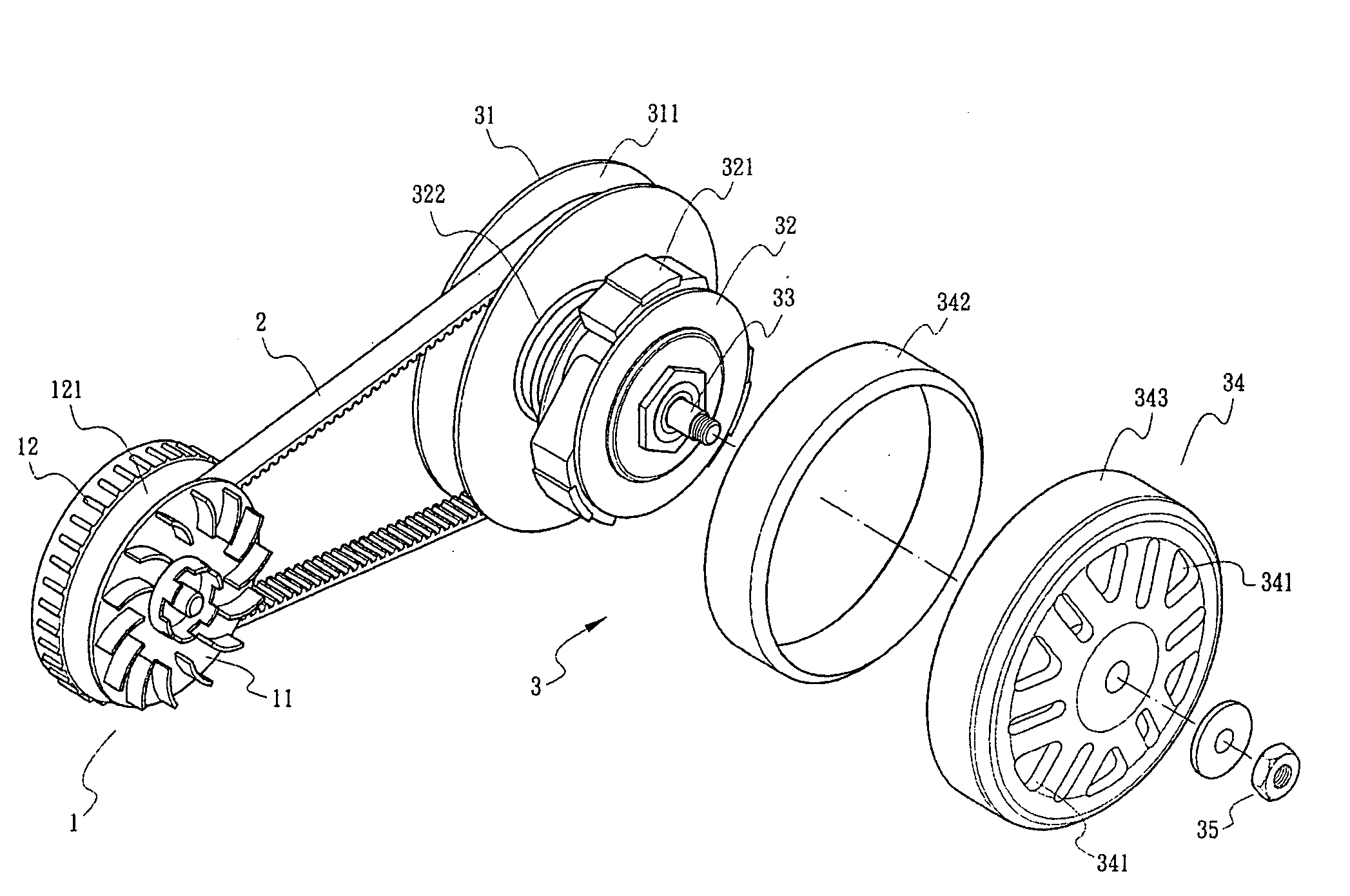
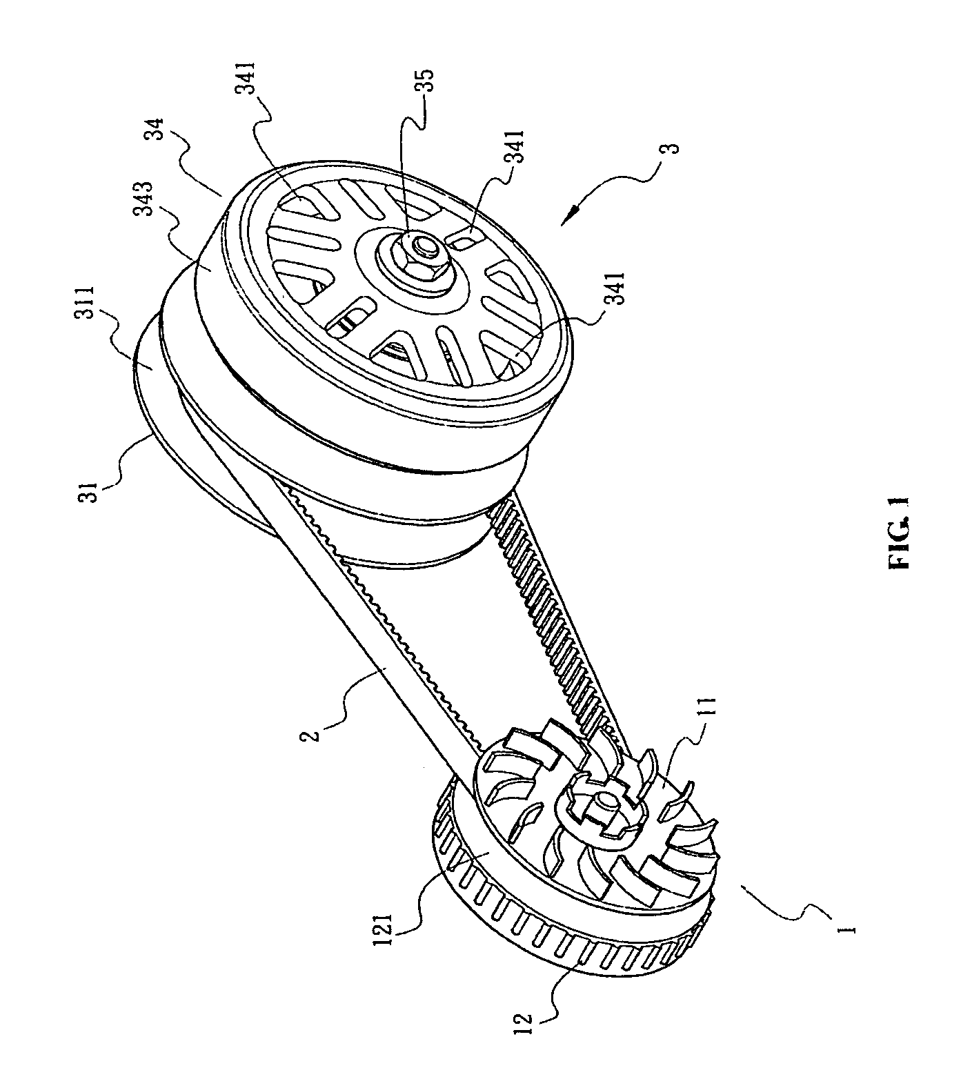
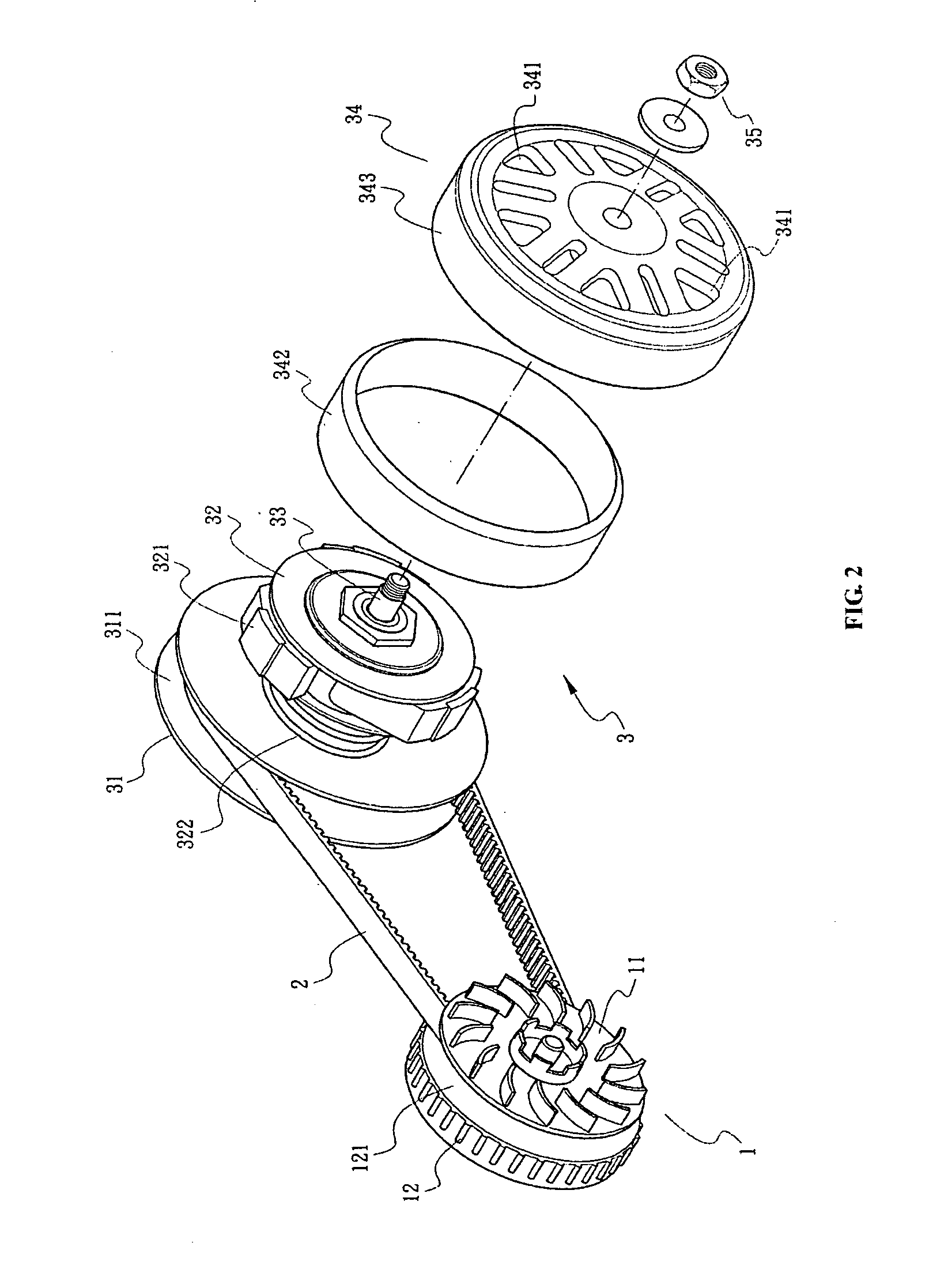
[0015]Referring to FIGS. 1 & 2, the improvement of the clutch housing structure of the present invention can be applied in a shift power transmission system; the shift power transmission system comprising a master wheel set 1, receiving driving power from engine connecting rod, which activates the clutch 3 through the transmission belt 2, and the power is transmitted to the boss 33 through the clutch disk 32, eventually to move the wheels; the master wheel set 1 is provided with a trench 121, and a belt 2 is hitched onto the trench 121, where the belt 2 has its other end encircle the clutch 3 into its trench 311; the clutch 3 is provided with a torque plate 31 and a clutch disk 32 with a plurality of clutch carriers 321, where the clutch disk 32 is embraced by a clutch housing 34.

[0016]The clutch housing 34 is designed into a hollow cylinder or a bowl shape with a hollow inside, and has a skirt portion 343; a washer 342 shaped in hollow cylinder, fixed onto the inner side of the ski...


PUM


Abstract

An improvement of the clutch housing structure, comprising a housing that fits the clutch carrier of the clutch disk, where the housing is provided with a skirt portion that embraces the clutch carrier; and a washer in rigid wall, which is fixed onto the inner side of the skirt portion of the housing, where the washer and the clutch carrier press each other to form a obstruction that characterizes high coefficient of friction, which further drives the boss to move the wheels; the target is to improve the imperfections of the prior art which includes the deformation at high temperature, or the skid and incomplete transmission by lacking of enough friction.

Description

BACKGROUND OF THE INVENTION[0001]1. Field of the Invention[0002]The present invention relates to clutch housing structures, more particularly, to one that is free of deformation subject to high temperature and not liable to skid.[0003]2. Background of the Invention[0004]CVT (Continuous Variable Transmission) is a fabulous power transmission system, where the utmost in advantage no doubt lies in its continuous non-gear shift, which characterizes a seamless transition during the changing of acceleration, enabling a direct and smooth transmission of the power, unlike ordinary gearshift systems, where a sizable difference between the gear ratio of its first gear and that of the second gear, which brings in the following drawbacks: considerable vibration at the moment of shifting gear, insufficient smoothness during power succession, unexpected deadlock of power transmission during shifting gear, lacking of immediate response for the accelerator, and more power consumption.[0005]The prin...

Claims


Application Information

Patent Timeline
Patent Type & Authority Applications(United States)
IPC IPC(8): F16D13/00
CPCF16D43/18F16D13/62
Inventor LIN, I
Owner LIN I
Learn More