Rail Car Sensor Network

Active Publication Date: 2009-07-09
IBM CORP
View PDF12 Cites 76 Cited by
  • Summary
  • Abstract
  • Description
  • Claims
  • Application Information

AI Technical Summary

Problems solved by technology

Unfortunately, position information does not provide more detailed data concerning the individual rail cars.
Moreover, monitoring rail cars parked on a

Method used


Image

  • Rail Car Sensor Network
  • Rail Car Sensor Network
  • Rail Car Sensor Network

Examples


Embodiment Construction

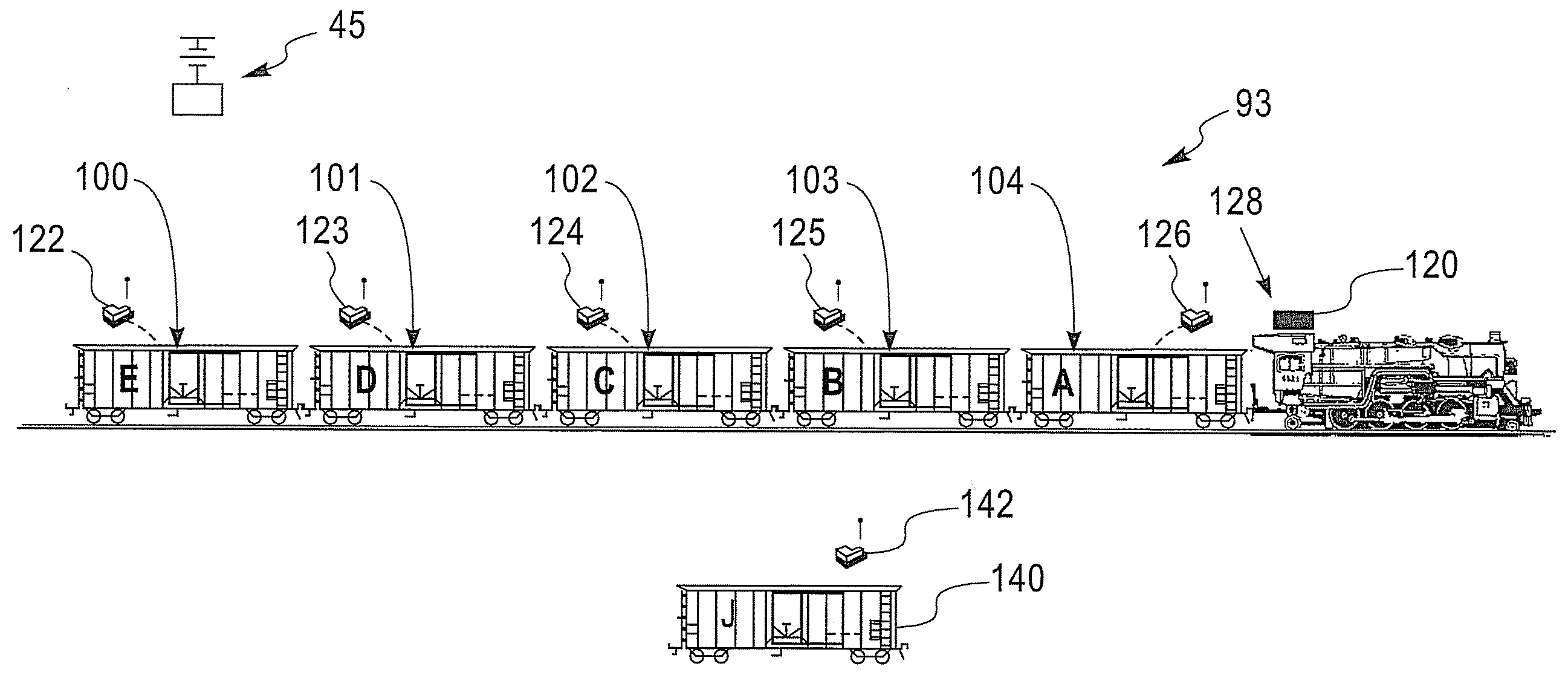
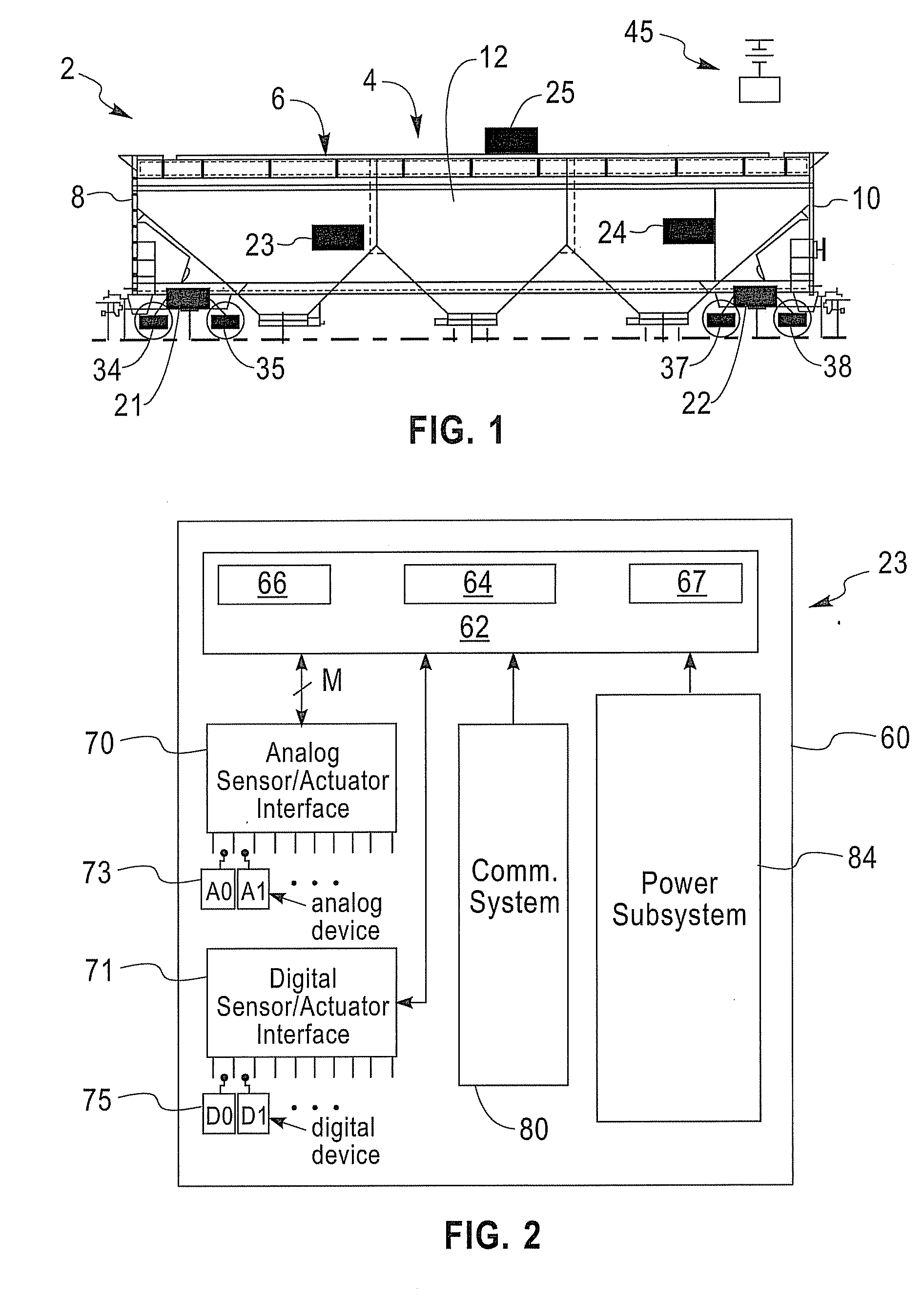
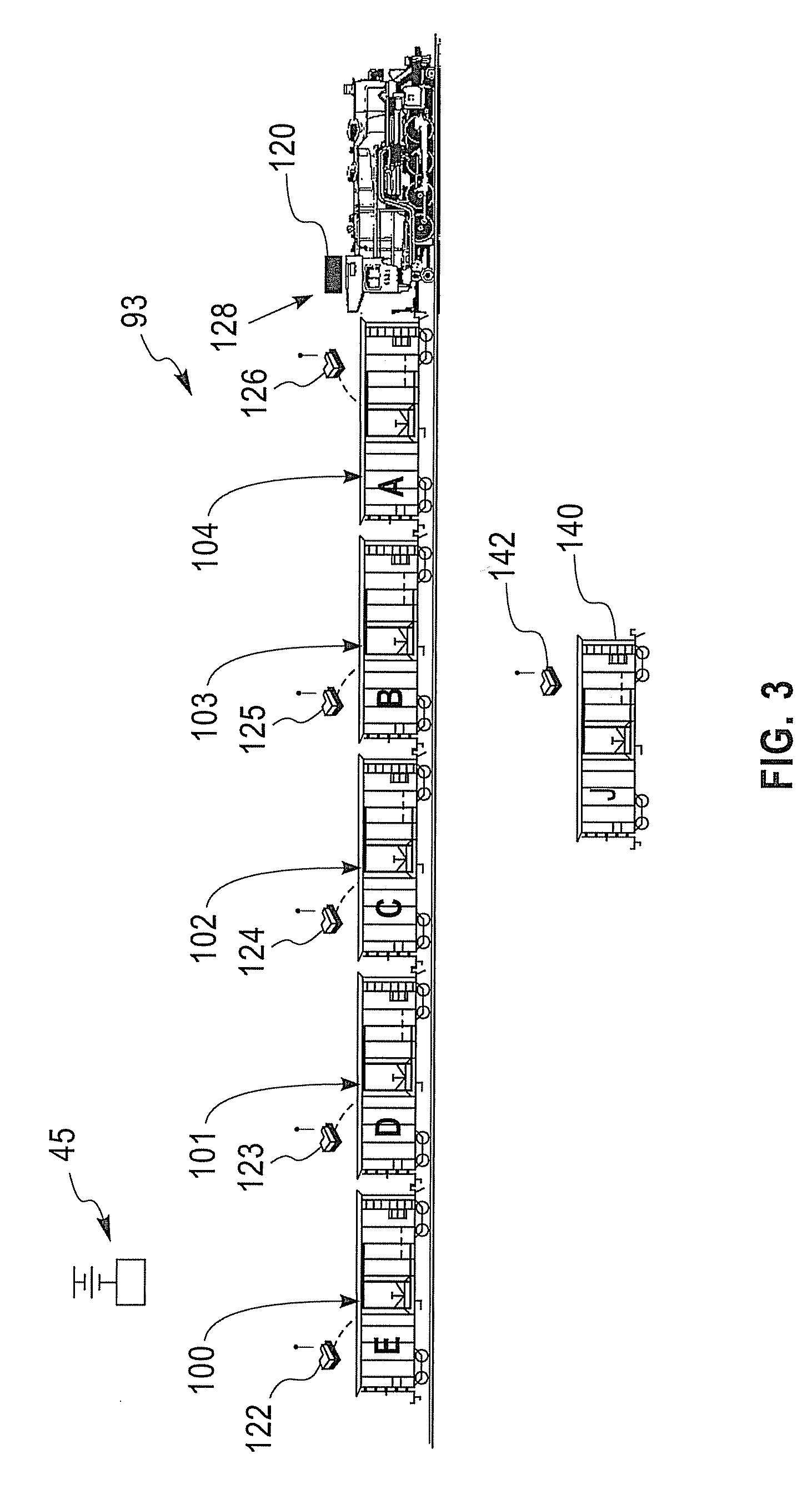
[0015]With initial reference to FIG. 1 a rail car sensor network, constructed in accordance with an exemplary embodiment of the present invention, is generally indicated at 2. Rail car sensor network 2 includes a rail car 4 having a main body portion 6 including a first end section 8, a second end section 10, and an intermediate section 12. Rail car 4 is provided with a plurality of motes or sensor assemblies 21-25 that are configured to detect various parameters associated with rail car 4. Examples of various configurations for sensor assemblies 21-25 include temperature sensing devices for sensing internal and external temperatures of rail car 4, location sensing devices using, for example, GPS signals to determine a location of rail car 4 geographically and signal strength sensors to determine the position of rail car 4 relative to other rail cars (not shown), direction of travel sensors, distance traveled sensors as well as vibration sensors. In addition to internal sensors that...


PUM


Abstract

A rail car sensor network, in accordance with an exemplary embodiment of the present invention, includes at least one rail car having a main body portion including a first and section, a second end section and an intermediate portion. The rail car network further includes a sensor assembly mounted to the rail car. The sensor assembly includes at least one sensor positioned to detect a rail car parameter, and a wireless communication device configured to transmit data corresponding to the rail car parameter. A receiver assembly, mounted remote from the at least one rail car, includes a wireless communication monitor configured to receive the data corresponding to the rail car parameter from the wireless communication device.

Description

BACKGROUND OF THE INVENTION[0001]1. Field of the Invention[0002]This invention relates to the art of rail car systems and, more particularly, to a rail car sensor network.[0003]2. Description of Background[0004]Everyday, in almost every country, thousands of rail cars travel overland delivering passengers and goods. Typically, the rail cars travel as part of a rail car system or train. A typical train includes one or more engines that pull (or push) the rail cars to a particular destination. The location, speed and itinerary of each train are monitored by sensing a position of the engine. The position of the engine is determined through track based sensors or via Global Positioning System (GPS) tracking. Unfortunately, position information does not provide more detailed data concerning the individual rail cars.[0005]At present, visual inspection is the method employed to determine a particular orientation of a rail car, a location / position of a particular rail car in a rail car syst...

Claims


Application Information

Patent Timeline
IPC IPC(8): B60Q9/00
CPCB61L15/0081B61L15/0027
Inventor BROWN, RICHARD H.DORN, JOHN Z.ELLIOTT, JEFFERY G.MOSKOWITZ, PAUL A.REASON, JONATHAN M.ZHU, XIANJIN
Owner IBM CORP
Why Eureka
Try Eureka