Support bracket for electrical box

a technology for supporting brackets and electrical boxes, which is applied in the direction of filing appliances, curing devices, furniture parts, etc., can solve the problems of relatively time-consuming installation of typical electrical boxes and conduits, and achieve the effect of efficient suspension and suppor

Active Publication Date: 2009-07-09
S P PRODS
View PDF10 Cites 7 Cited by
  • Summary
  • Abstract
  • Description
  • Claims
  • Application Information

AI Technical Summary

Benefits of technology

[0007]The unitary support plate further includes a plurality of leg portions extending integrally from the central portion. Each of the leg portions includes a horizontal portion extending integrally from the central portion, and a deformable distal portion extending from the respective horizontal portion. Notably, each of the distal portions defines a plurality of deformable tab elements engageable with respective ones of the conduits associated with the electrical box. Additionally, each leg portion is preferably scored at the juncture of the distal portion with the horizontal portion thereof, to thereby facilitate downward deformation of the distal portion. In this manner, the distal portion of each leg portion is downwardly deformable from the respective horizontal portion to extend downwardly therefrom generally at a right angle. Conduits which extend horizontally from the electrical box can thus be efficiently and conveniently assembled with the electrical box, and supported generally by the downwardly extending distal portion of each of the leg portions.
[0008]In the preferred form, the horizontal portion of each leg portion includes at least gusset for enhancing rigidity thereof, thereby desirably permitting the support plate to exhibit the necessary strength, while allowing manufacture from a relatively thinner gage of metal. Additionally, the horizontal portion of each leg portion preferably defines a plurality of laterally spaced openings, which correspond in spacing to the spacing of knock-out openings provided in the sides of the electrical box. Such openings can be non-threaded, to permit the insertion of self-tapping screws or the like therein, or the openings can be threaded to facilitate the provision of clamps or the like for securing the associated conduits in position.
[0009]Notably, the present support plate can be configured in two different forms, with one form including four of the leg portions, and the other form including two of the leg portions. In the first form, the for leg portions extend from the central portion, and are spaced at right angles to each other. In this embodiment, the support plate is preferably scored at the juncture of each of the leg portions with the central portion, to thereby facilitate separation of any selected one or more of the leg portions from the central portion. Thus, the support bracket can be readily customized for any particular arrangement of conduits which are fitted to the electrical box.
[0011]In both embodiments of the present support bracket, the central portion of the support plate preferably defines at least one opening through which an associated conduit can extend generally vertically through the support plate. Such openings are preferably spaced to correspond to “knock-out” openings typically provided in the back side (top) of electrical boxes, thereby facilitating convenient and efficient joining of conduits to the electrical box, with the conduits extending generally vertically from the box.

Problems solved by technology

As such, installation of typical electrical boxes and conduits can be relatively time-consuming, as workers must fit and assemble the various brackets, clamps, and like components to ensure that the resultant structure is in accordance with industry standards.

Method used


Image

  • Support bracket for electrical box
  • Support bracket for electrical box
  • Support bracket for electrical box

Examples


Embodiment Construction

[0020]While the present invention is susceptible of embodiment in various forms, there is shown in the drawings, and will hereinafter be described, presently preferred embodiments, with the understanding that the present disclosure is to be considered as an exemplification of the invention, and is not intended to limit the invention to the specific embodiments illustrated.

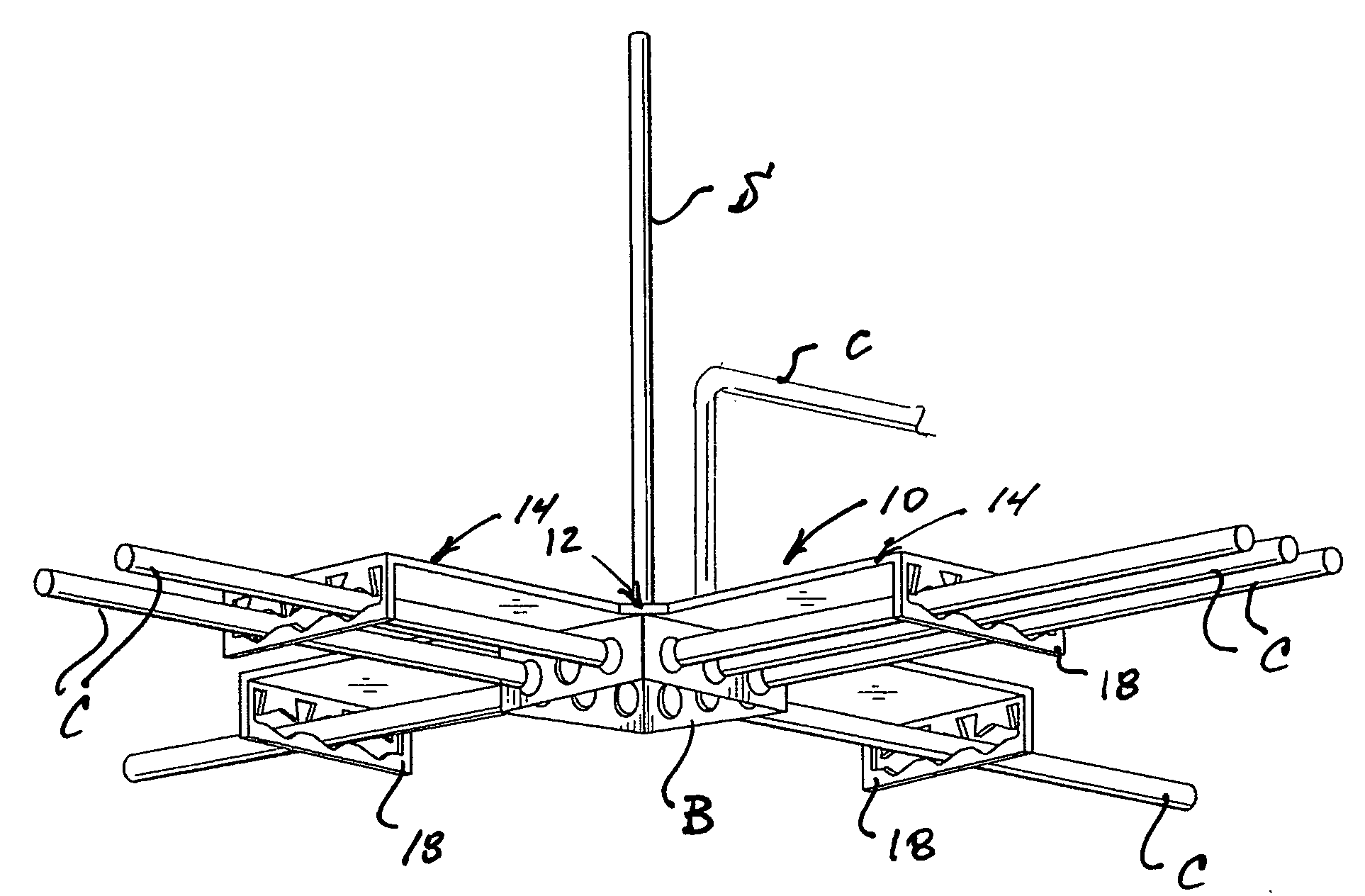
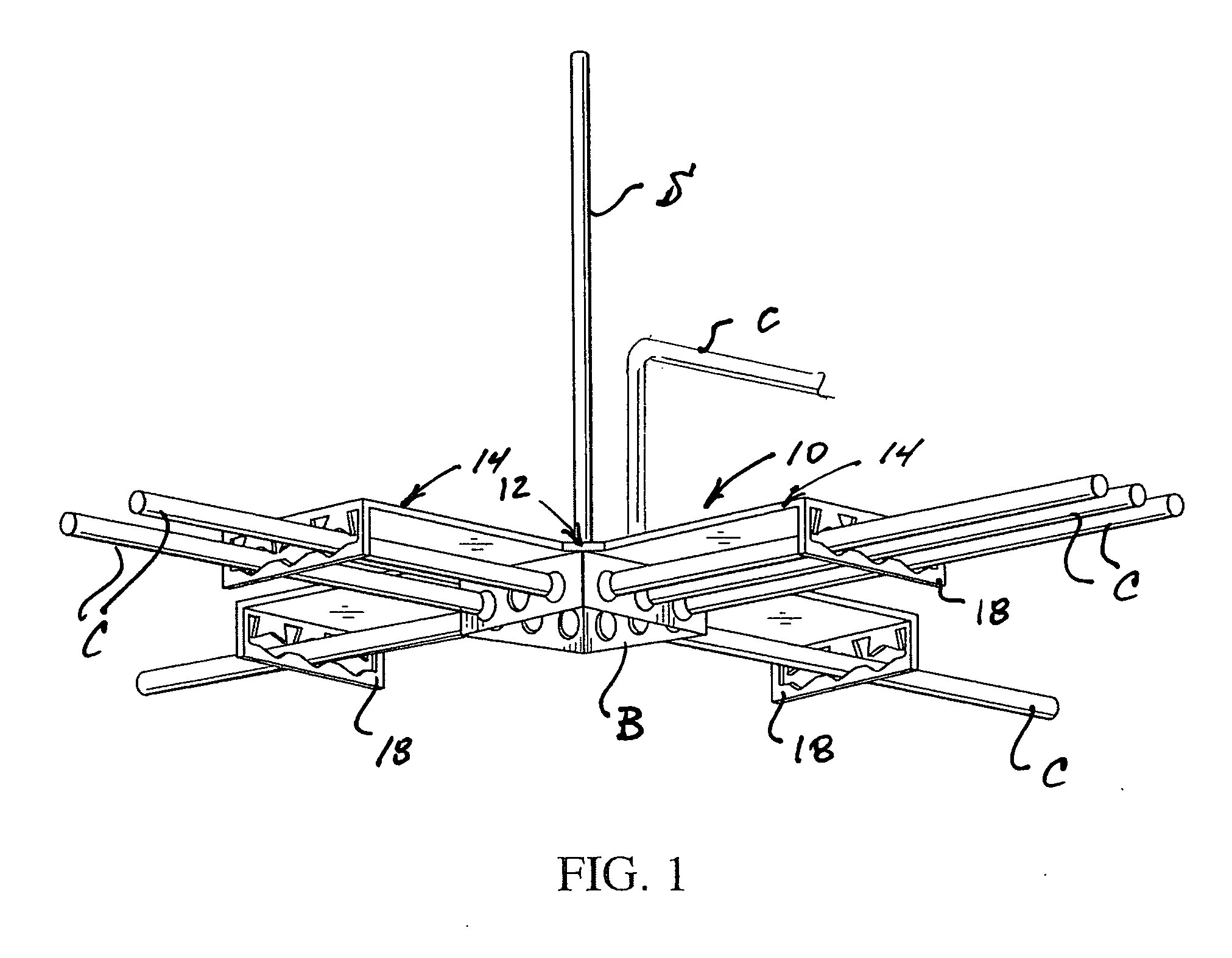
[0021]With reference to drawings, therein as illustrated a support bracket 10 configured for supporting an associated electrical box B, and associated conduits C operatively connected with the electrical box. As will be recognized by those familiar with the art, the typical arrangement of the electrical box and associated conduits is one in which the electrical box is supported from an associated vertical support S, with the conduits extending generally horizontally from the sides of the electrical box. Additionally, the illustrated installation includes a conduit C extending generally vertically from the electrica...


PUM


Abstract

A unitary support bracket facilitates secure and efficient support of an electrical box, and one or more associated conduits. The support bracket includes a central portion, and a plurality of leg portions which extend integrally therefrom. Each of the leg portions includes a downwardly deformable distal portion, which in turn each include at least one resiliently deformable tab engageable with a respective one of the conduits. By this arrangement, the efficient support of an electrical box, and one or more associated conduits, can be provided, with minimal assembly of various components required, thus facilitating convenient and efficient installation of the associated electrical system.

Description

[0001]The present invention relates generally to an arrangement for supporting an electrical junction box, and associated conduits, and more particularly to an improved unitary support bracket for an electrical box, which can be selectively configured to facilitate efficient and convenient assembly and support of associated conduits, including conduits extending in four different horizontal directions from the electrical box, as well as one or more conduits extending vertically therefrom.BACKGROUND OF THE INVENTION [0002]In the typical construction of a building structure, electrical wiring for the structure is typically routed through various conduits, with the conduits commonly joined to an electrical box, within which suitable electrical connections or the like are provided. As will be recognized by those familiar with the art, typical building codes require that such conduits and electrical boxes meet certain structural requirements, including spacing, support, and like requirem...

Claims


Application Information

Patent Timeline
Patent Type & Authority Applications(United States)
IPC IPC(8): A47B96/06B42F13/00
CPCH02G3/381H02G3/20Y10S248/906
Inventor VRAME, PETER A.VRAME, PAUL A.
Owner S P PRODS
Why Eureka
Try Eureka