Methods for adjusting frequency of piezoelectric vibrating pieces, piezoelectric devices, and tuning-fork type piezoelectric oscillators

a technology of piezoelectric vibrating pieces and tuning forks, which is applied in the direction of piezoelectric/electrostrictive device details, piezoelectric/electrostrictive/magnetostrictive devices, piezoelectric/electrostriction/magnetostriction machines, etc., which can solve the problem of generating spurious undesired vibration frequencies, affecting the yield of manufacturing processes, and affecting the ci value of tuning for

Inactive Publication Date: 2009-07-09
NIHON DEMPA KOGYO CO LTD
View PDF5 Cites 17 Cited by
  • Summary
  • Abstract
  • Description
  • Claims
  • Application Information

AI Technical Summary

Benefits of technology

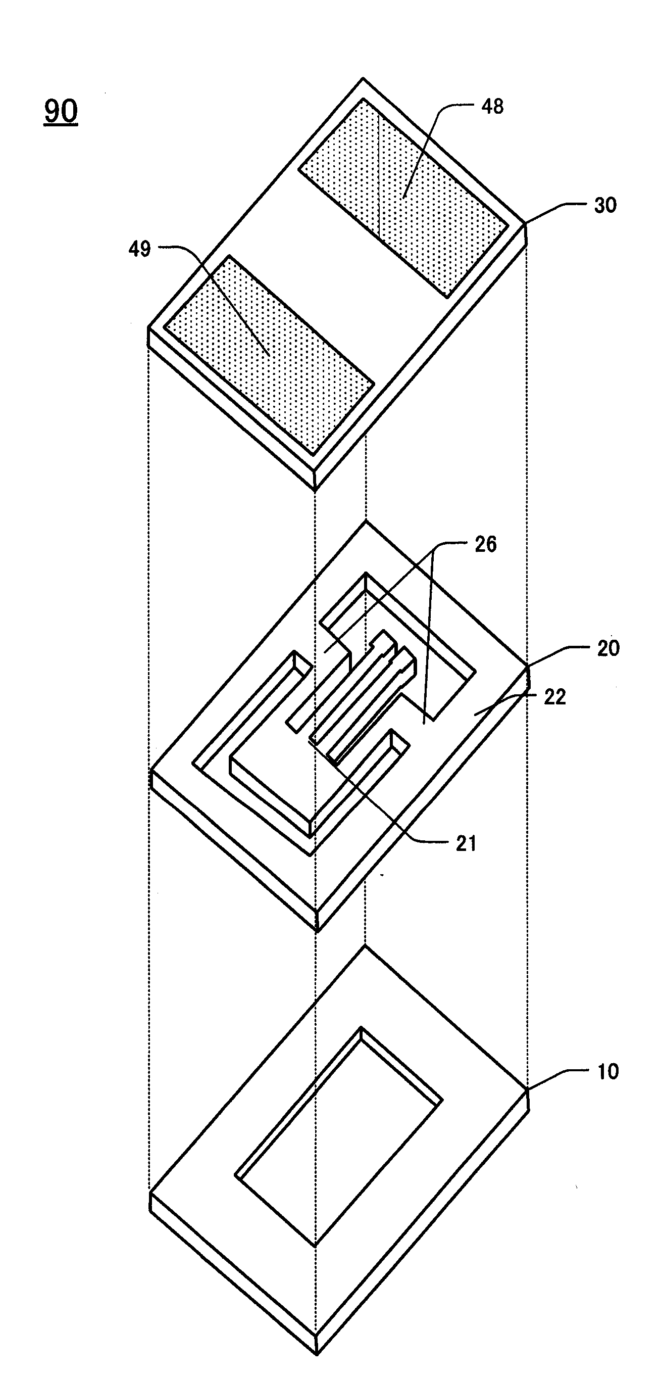
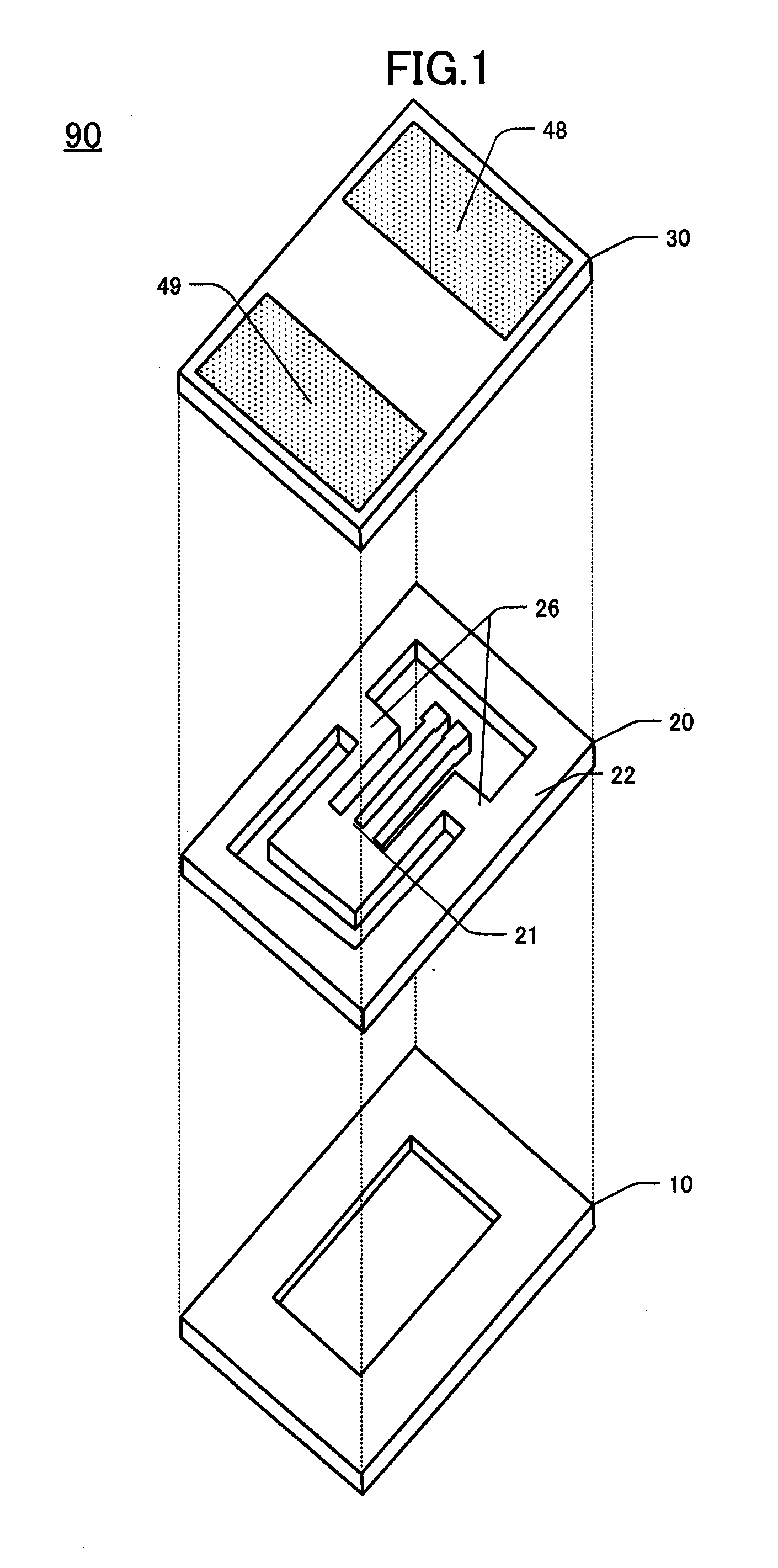
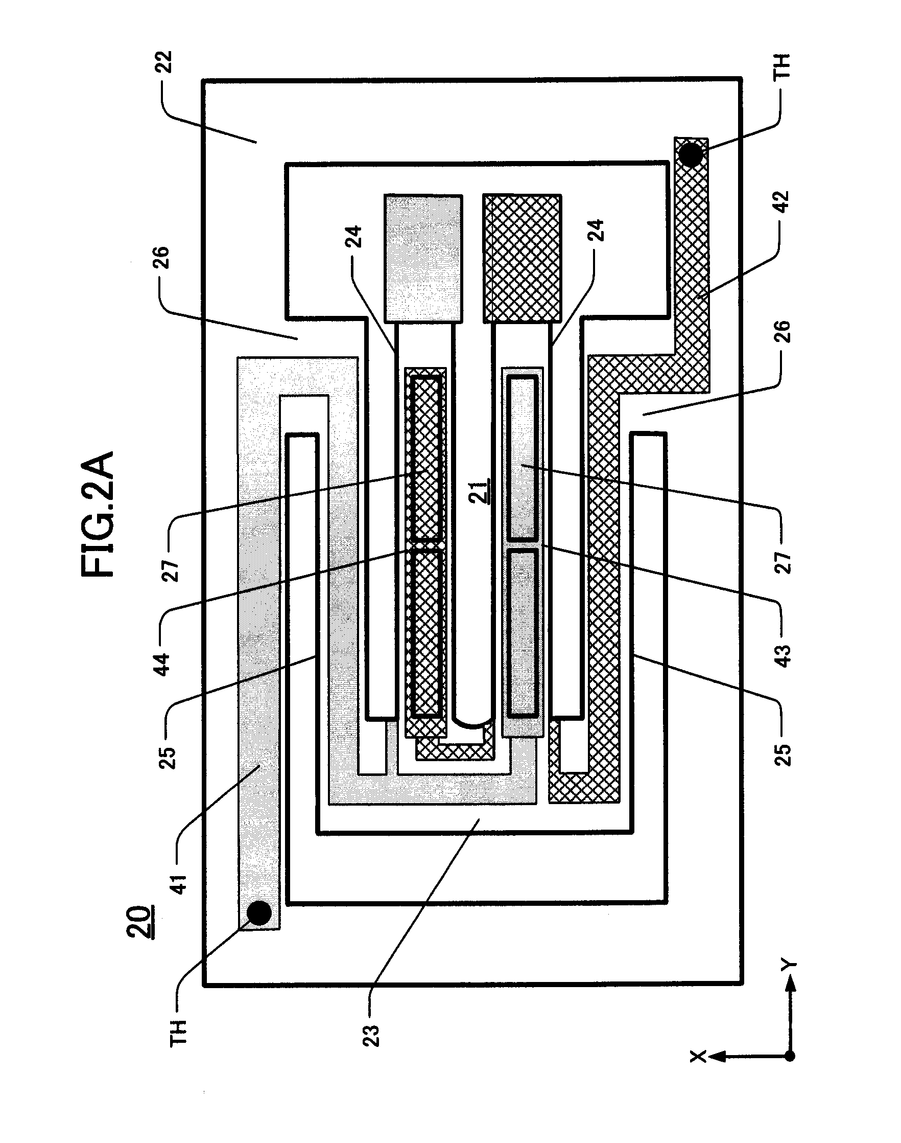
[0008]This disclosure sets forth several aspects of the invention. A first aspect pertains to a piezoelectric frame comprised of a tuning-fork type piezoelectric vibrating piece comprising a base portion, at least a pair of vibrating arms extending in a first direction from one edge of the base portion, and respective excitation electrodes on the vibrating arms. A respective supporting arm extends in the first direction from an external edge of each vibrating arm. An outer frame portion surrounds the tuning-fork type piezoelectric vibrating p

Problems solved by technology

The evaporated material may also cause the CI value of the tuning-fork type piezoelectric vibrating piece to change after completion of the oscillation frequency adjustment or may generate spurious undesired vibration frequencies.
Increasing the CI and/or generating spurious vibrations deteriorates the qualit

Method used


Image

  • Methods for adjusting frequency of piezoelectric vibrating pieces, piezoelectric devices, and tuning-fork type piezoelectric oscillators
  • Methods for adjusting frequency of piezoelectric vibrating pieces, piezoelectric devices, and tuning-fork type piezoelectric oscillators
  • Methods for adjusting frequency of piezoelectric vibrating pieces, piezoelectric devices, and tuning-fork type piezoelectric oscillators

Examples


fourth embodiment

ent Method

[0073]As described in the second and third embodiments, frequency adjustment is conducted during manufacture of the piezoelectric devices, FIG. 5A shows frequency adjustment being conducted on the crystal frame 20 having connecting portions using, for example, a femtosecond-pulsed laser FL. Vibration frequency is changed by cutting away a portion of the connecting portion 26 in the Y-direction. Cutting is conducted on both connecting portions 26, shown as having respective widths W1 and W2. Both widths W1, W2 are the same. FIGS. 5A-5D show enlargements of detail within the area of the dashed-line circle KA of FIG. 5A.

[0074]FIG. 5B shows frequency adjustment being performed by cutting away a part DE of the connecting portion 26 closer to the base portion. FIG. 5C shows frequency adjustment being performed by cutting away a part DE of the connecting portion closer to the tip of vibrating arm. FIG. 5C is an alternative procedure to that shown in FIG. 5B. FIG. 5D shows frequen...


PUM


Abstract

A piezoelectric frame includes a tuning-fork type piezoelectric vibrating piece having excitation electrodes on each of at least two vibrating arms extending in a first direction from one end of a base portion thereof. Respective supporting arms extend in a first direction from respective external edges of the vibrating arms. An outer frame portion surrounds the tuning-fork type piezoelectric vibrating piece. The connecting portions have designated widths and connect the respective supporting arms to the outer frame portion. During manufacture, the designated widths are trimmed (e.g., by a pulsed laser) until the desired vibration frequency is obtained.

Description

CROSS-REFERENCE TO RELATED APPLICATION[0001]This application claims priority to, and the benefit of, Japan Patent Application No. 2008-002174, filed on Jan. 9, 2008, in the Japan Patent Office, the disclosure of which is incorporated herein by reference in its entirety.FIELD[0002]This invention is related to, inter alia, methods for manufacturing tuning-fork type piezoelectric vibrating elements having supporting arms which controls frequency adjustment by using a piezoelectric substrate made of crystal,DESCRIPTION OF THE RELATED ART[0003]With the progress of miniaturization and / or increases in the operating frequency of mobile communication apparatus and office automation (OA) equipment, piezoelectric oscillators used in this equipment must be progressively smaller and / or operate at higher frequency. Also required are piezoelectric oscillators that can be surface mounted (SMD: Surface Mount Device) on circuit boards. The manufacturing process of miniaturized piezoelectric vibrating...

Claims


Application Information

Patent Timeline
IPC IPC(8): H01L41/04
CPCH03H3/04H03H9/0595H03H2009/02165H03H9/21H03H2003/0492H03H9/1035
Inventor YOSHIMATSU, MASAHIROONO, KOZOUEHARA, HIROSHITAKEUCHI, TOSHIAKI
Owner NIHON DEMPA KOGYO CO LTD
Why Eureka
Try Eureka