Method and apparatus for setting active period starting point for user equipment
a technology for user equipment and starting points, applied in the field of user equipment starting points, can solve the problems of discontinuous data arriving at users, limited stored power, and limited drx time at which the user receives downlink data, so as to eliminate the adverse effects of the drx mode of the user equipment on resource utilization, avoid uneven resource utilization, and improve system capacity
- Summary
- Abstract
- Description
- Claims
- Application Information
AI Technical Summary
Benefits of technology
Problems solved by technology
Method used
Image
Examples
first embodiment
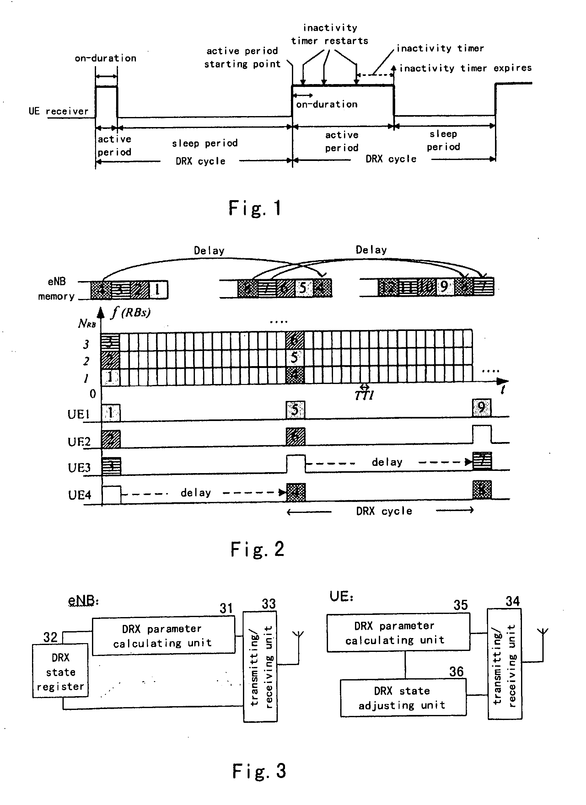
[0040]FIG. 3 is a block diagram showing an apparatus for voluntarily setting an active period starting point by a user according to the first embodiment of the present invention. As shown in FIG. 3, the apparatus for voluntarily setting the active period starting point by the user according to this preferred embodiment comprises a discontinuous reception (DRX) parameter calculating unit 31, a DRX state register 32, and a transmitting / receiving unit 33 at the network side (eNB: source node or base station), as well as a transmitting / receiving unit 34, a DRX parameter calculating unit 35, and a DRX state adjusting unit 36 at the UE side.
[0041]At the eNB side, the transmitting / receiving unit 33 (which may be a first transmitting / receiving unit) is adapted to transmit and receive information from a radio interface. The DRX parameter calculating unit 31 (which may be a first DRX parameter calculating unit) is adapted to determine DRX configuration information of the UE. The configuration...
second embodiment
[0047]FIG. 6 is a block diagram showing an apparatus for setting an active period point for the UE by the eNB according to the second embodiment of the present invention. As shown in FIG. 6, the apparatus for setting the active period point for the UE by the eNB according to this preferred embodiment comprises a discontinuous reception (DRX) parameter calculating unit 61, a DRX configuration packaging unit 62, a DRX state register 63, and a transmitting / receiving unit 64 at the network side (eNB: source node or base station), as well as a transmitting / receiving unit 65, and a DRX state adjusting unit 66 at the UE side.
[0048]At the eNB side, the DRX parameter calculating unit 61 may calculate the active period starting point for the UE in the DRX state with equation (1) as described above, and stores the calculation result in the DRX state register 63 or updates the DRX state register 63 with the calculation result. The DRX configuration packaging unit 62 packages the calculated acti...
third embodiment
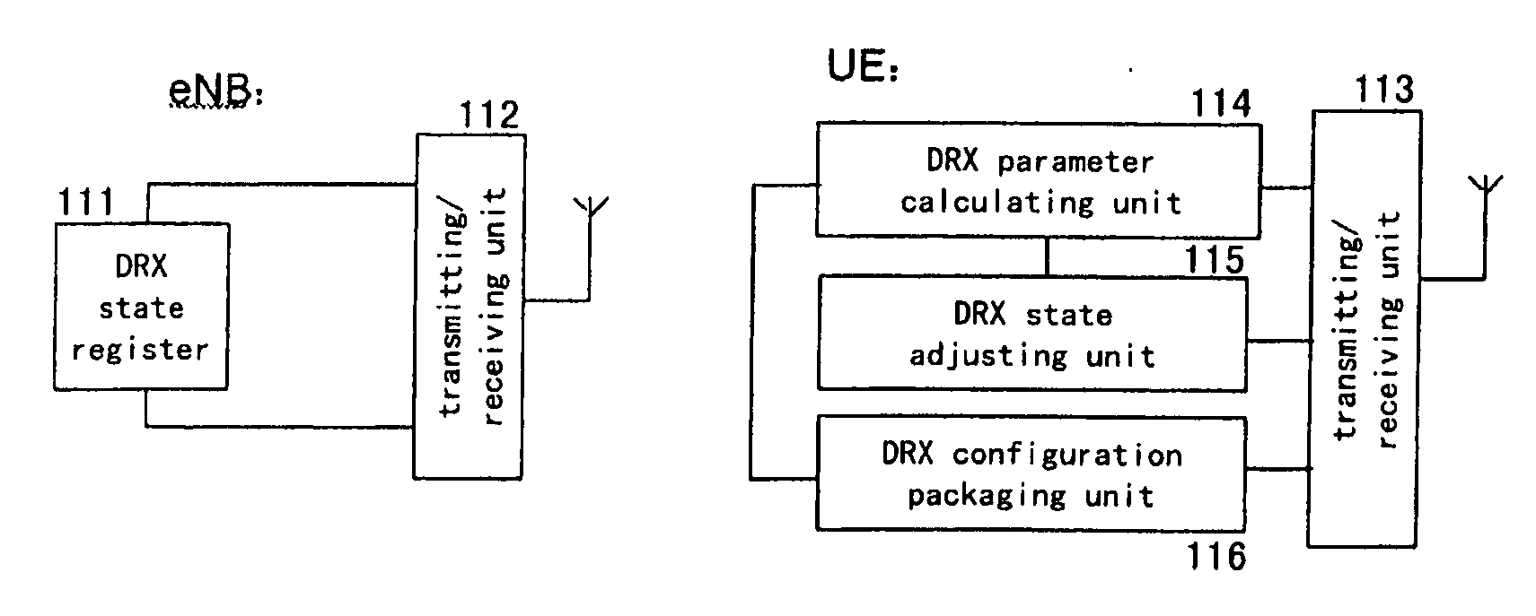
[0058]FIG. 11 is a block diagram showing an apparatus for voluntarily setting an active period starting point by the UE and notifying the eNB according to the third embodiment of the present invention. As shown in FIG. 11, the apparatus for voluntarily setting the active period starting point by the user according to this preferred embodiment comprises a DRX state register 111 and a transmitting / receiving unit 112 at the network side (eNB: source node or base station), as well as a transmitting / receiving unit 113, a DRX parameter calculating unit 114, a DRX state adjusting unit 115, and a DRX configuration packaging unit 116 at the UE side.
[0059]In contrast to the above first and second embodiments, the DRX state register 111 and the transmitting / receiving unit 112 are provided at the eNB side. The eNB stores the DRX configuration information received by the transmitting / receiving unit 112, including the active period starting point calculated by the UE, in the DRX state register 11...
PUM
 Abstract
Description
Claims
Application Information
 - R&D
- Intellectual Property
- Life Sciences
- Materials
- Tech Scout
- Unparalleled Data Quality
- Higher Quality Content
- 60% Fewer Hallucinations
Browse by: Latest US Patents, China's latest patents, Technical Efficacy Thesaurus, Application Domain, Technology Topic, Popular Technical Reports.
© 2025 PatSnap. All rights reserved.Legal|Privacy policy|Modern Slavery Act Transparency Statement|Sitemap|About US| Contact US: help@patsnap.com


