Image forming apparatus
- Summary
- Abstract
- Description
- Claims
- Application Information
AI Technical Summary
Benefits of technology
Problems solved by technology
Method used
Image

Examples
first embodiment
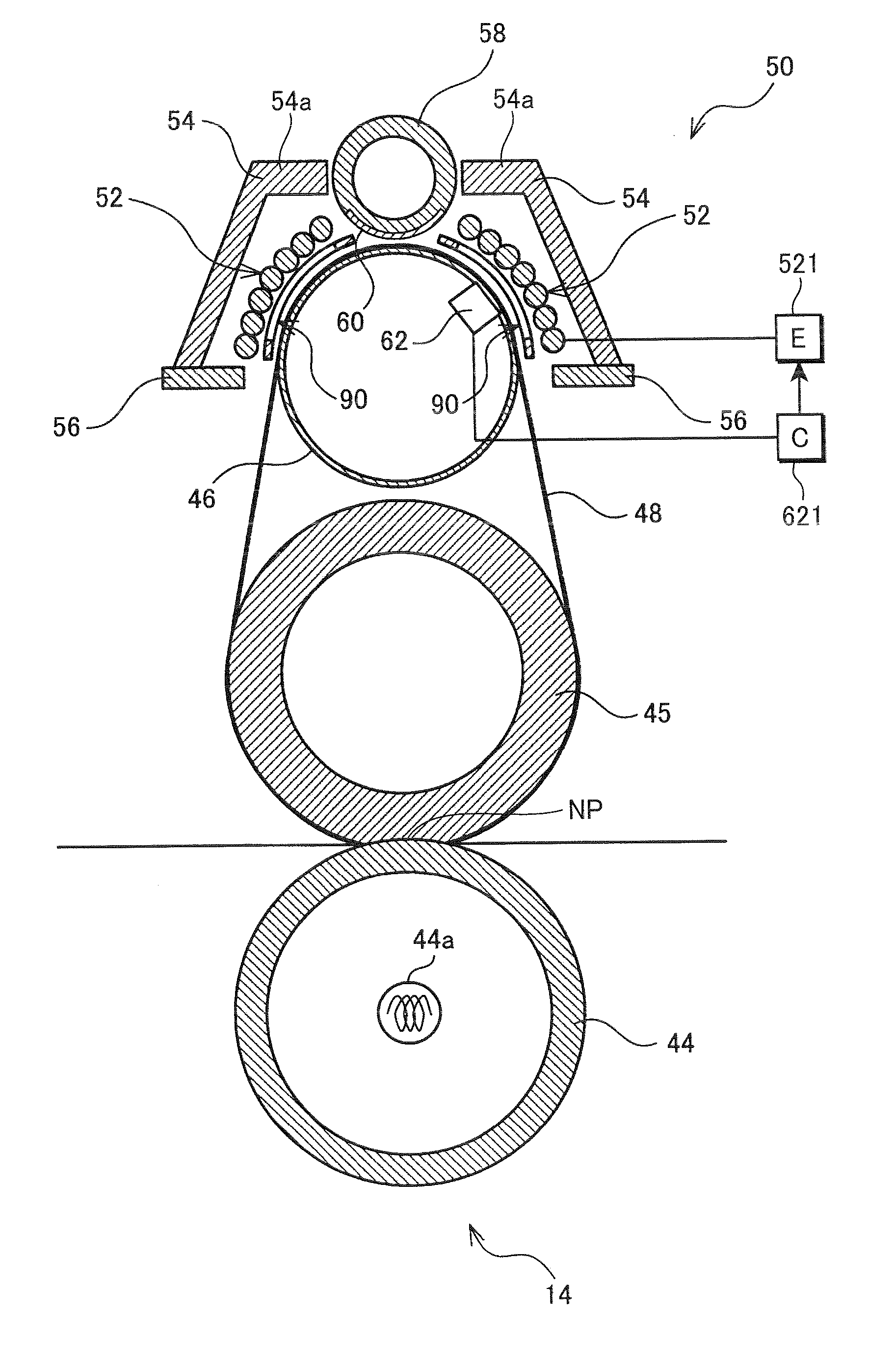
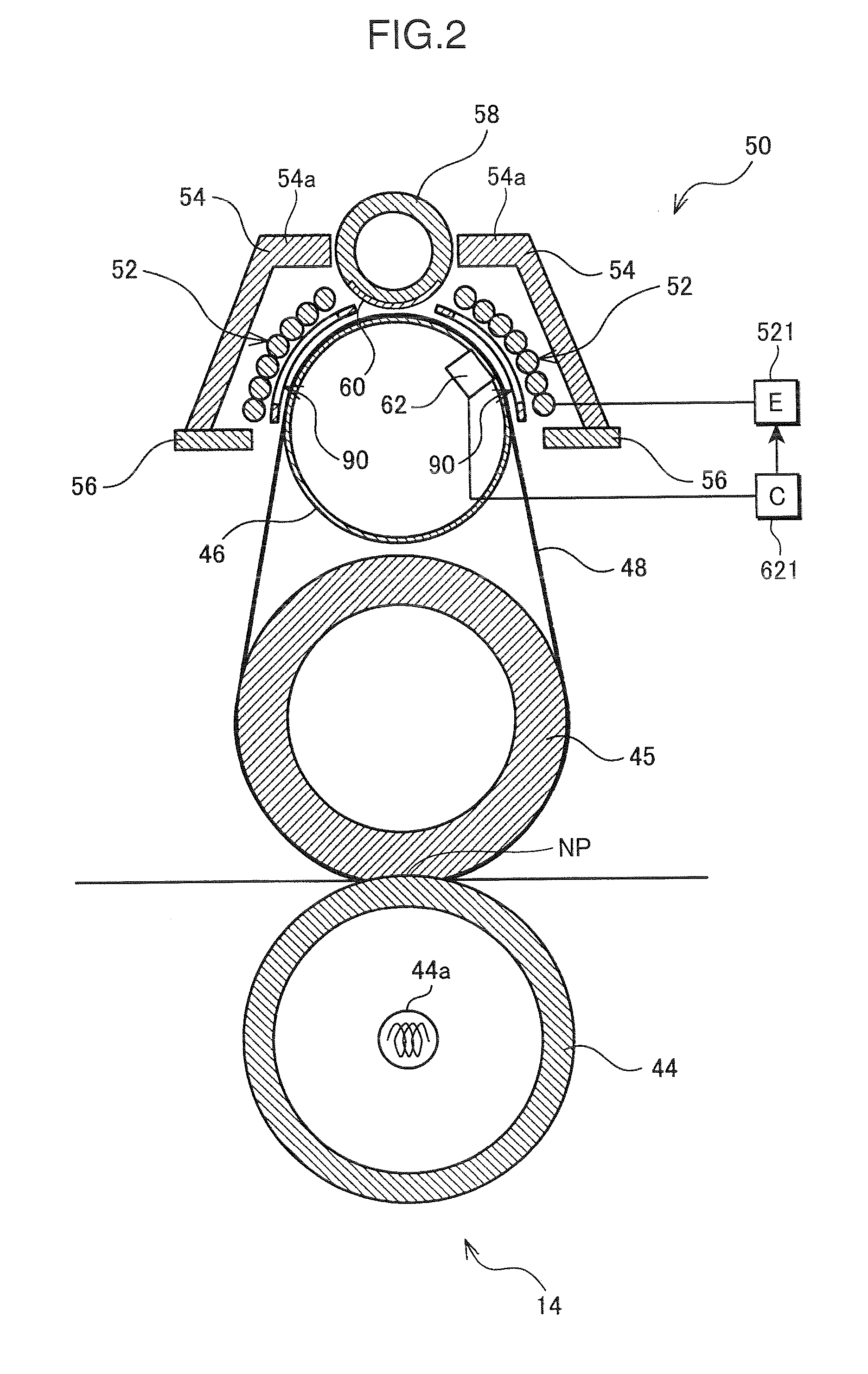
[0054]FIG. 2 is a vertical section showing the fixing unit 14 of the first embodiment. In a state shown in FIG. 2, the orientation of the fixing unit 14 is rotated counterclockwise by about 90° from an actually mounted state in the image forming apparatus 1. Accordingly, the sheet conveying direction from lower side to upper side in FIG. 1 is from right side to left side in FIG. 2. If the apparatus main body 2 has a larger size (complex machine or the like), the fixing unit 14 may be actually mounted in the orientation shown in FIG. 2.
[0055]The fixing unit 14 includes the pressure roller 44, the fixing roller 45, the heat roller 46 and the heating belt 48 as described above. As described above, the pressure roller 44 is made of a metal, but the fixing roller 45 includes the elastic layer of silicon sponge on the outer layer. Thus, a flat nip NP is formed between the heating belt 48 and the fixing roller 45. It should be noted that a halogen heater 44a is disposed in the pressure rol...
first modification
[0102]FIG. 12 is a diagram showing the first modification of the fixing unit 14 of the first embodiment. In this first modification, a toner image is fixed by the fixing roller 45 and the pressure roller 44 without using the heating belt 48 and the heat roller 46. A magnetic body similar to the above heating belt is, for example, wound around the outer circumferential surface of the fixing roller 45, and the magnetic body is induction heated by the induction heating coil 52. In this case, the thermistor 62 is disposed at a position outside the fixing roller 45 to face a layer of the magnetic body. The rest is similar to the above and the magnetic shielding amount can be adjusted by rotating the center core 58. The magnetism adjusting members 90 are arranged between the induction heating coil 52 and the fixing roller 45.
second modification
[0103]FIG. 13 is a diagram showing the second modification of the fixing unit 14 of the first embodiment. This second modification differs from the first modification in that the heat roller 46 is made of a nonmagnetic metal material (e.g. SUS: stainless steel) and the center core 58 is arranged inside the heat roller 46. In addition, the arch cores 54 are connected in the center and an intermediate core 55 is disposed below the arch cores 54. Further, the magnetism adjusting members 90 are arranged between the induction heating coil 52 and the heating belt 48.
[0104]If the heat roller 46 is made of the nonmagnetic metal, the magnetic field generated by the induction heating coil 52 passes the side cores 56, the arch cores 54 and the intermediate core 55 and passes through the heat roller 46 to reach the center core 58 inside. The heating belt 48 is induction heated by the penetrating magnetic field.
[0105]In the case of the second modification, the shielding members 60 are distanced ...
PUM
 Abstract
Description
Claims
Application Information