
Diagnostic tool for an energy conversion appliance

a technology of energy conversion appliances and diagnostic tools, which is applied in the direction of mechanical roughness/irregularity measurements, instruments, electric digital data processing, etc., can solve the problems of compromising the integrity of the control or, at least, being very time-consuming in installation, and achieves the effect of easy installation into an existing appliance and simple installation

Inactive Publication Date: 2009-07-09
INVENSYS CONTROLS UK
View PDF8 Cites 5 Cited by
  • Summary
  • Abstract
  • Description
  • Claims
  • Application Information

AI Technical Summary

Benefits of technology

Enables easy retrofitting and minimally intrusive installation, providing comprehensive diagnostic data for predictive maintenance, reducing system problems and rapid fault repair, and allowing for timely component replacement and shutdown alerts.

Problems solved by technology

The intrusive nature of this activity potentially compromises the integrity of the control or, at the least, is very time consuming in installation.

Method used


Image

  • Diagnostic tool for an energy conversion appliance
  • Diagnostic tool for an energy conversion appliance
  • Diagnostic tool for an energy conversion appliance

Examples


Embodiment Construction

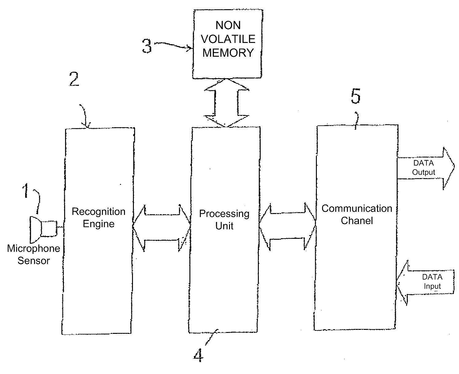
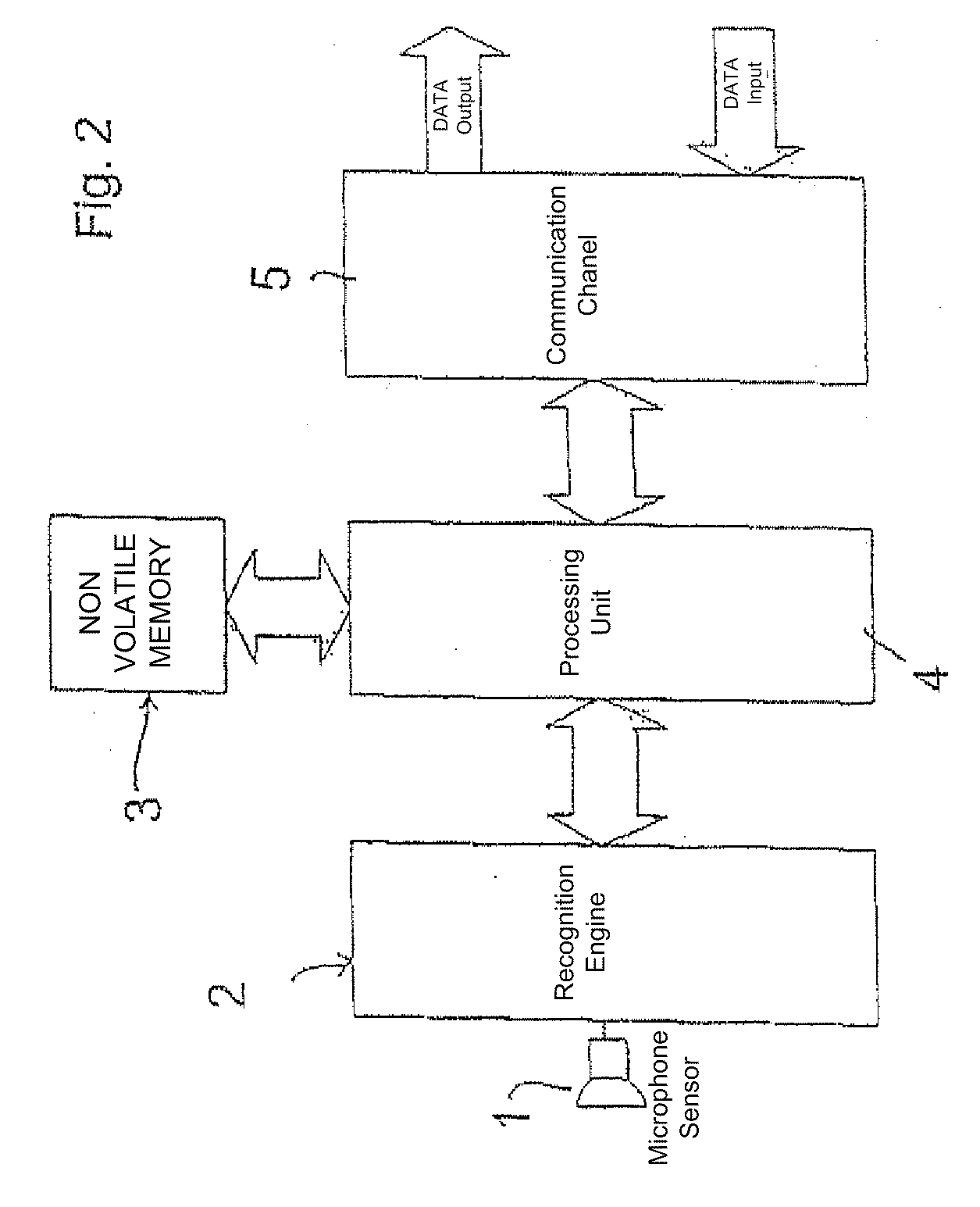
[0017]In accordance with one aspect of the present invention there is provided a diagnostic tool for an energy conversion appliance said diagnostic tool comprising a sound receiver transducer coupled to a sound recognition engine, alternatively referred to herein as output means, to identify, discriminate and log the acoustic signatures of events within the operating sequence of an appliance.

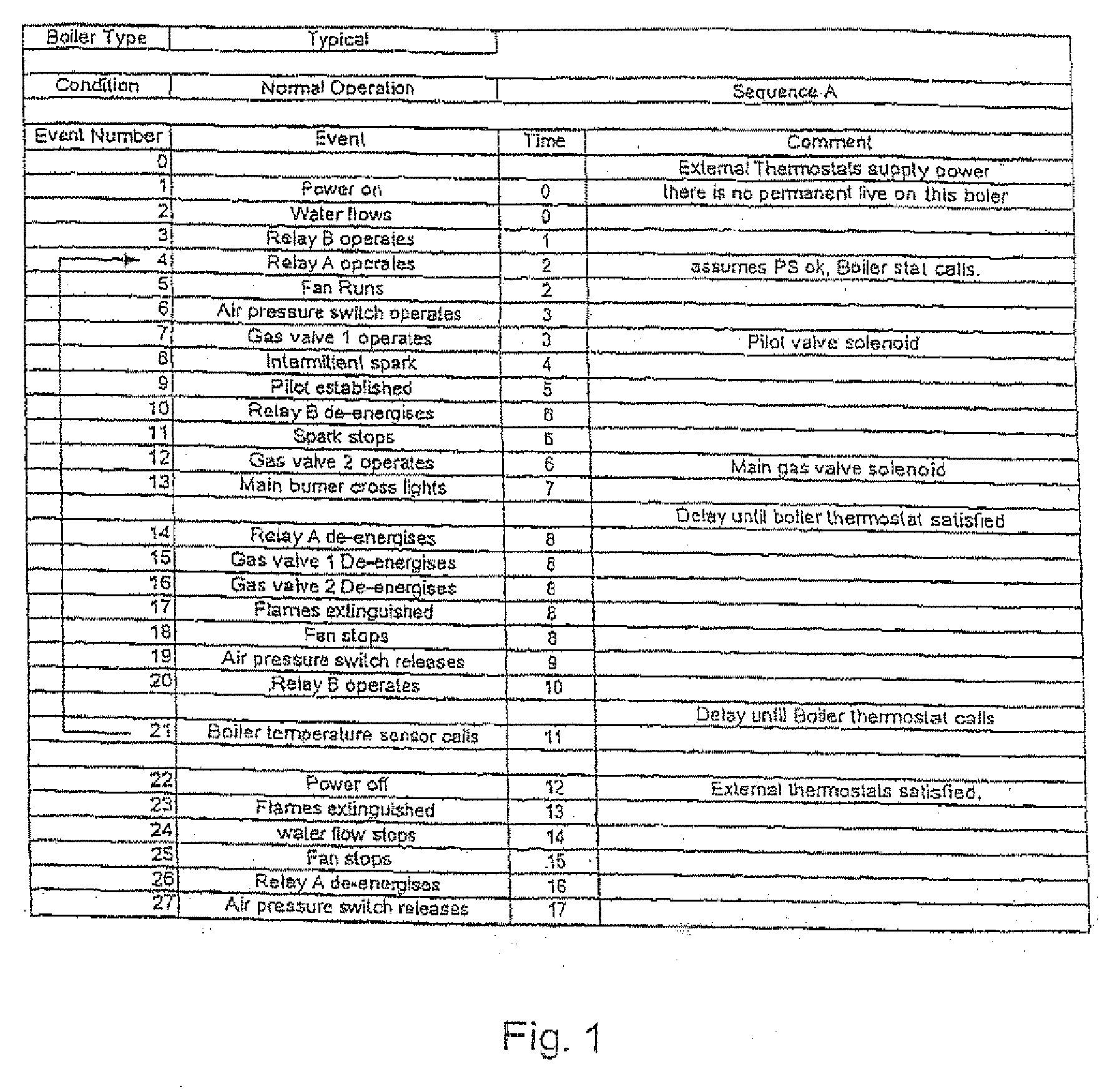
[0018]The word “event” is used herein to encompass a change of state of a component, or components, of the operating or control system of the appliance. As an example FIG. 1 tabulates a typical event sequence of a simple domestic gas central heating boiler.

[0019]The sound recognition engine may be an adaptation of a voice recognition type system known per se. These systems, commonly found in mobile telephones and other applications requiring voice tagging or control, are very robust in the presence of background noise and the technology is becoming increasingly well known and reliable.

[0020]In a...


PUM


Abstract

A diagnostic tool for an energy conversion appliance, which may be a heating, ventilating or air conditioning appliance, comprises a sound receiving transducer (1) coupled to output means (5) to identify, discriminate and log the acoustic signatures of a sequence of events within an operating sequence of an appliance. Individual event occurrences are identified by comparison of a received acoustic signature with stored data to determine whether an event occurrence has occurred in a proper manner and at a correct position in the sequence of a plurality of event occurrences.

Description

[0001]This application is a divisional application of Ser. No. 10 / 529,178, filed Mar. 24, 2005, currently pending, which claims priority to PCT / GB2003 / 004059, filed Sep. 23, 2003, which claims priority to Great Britain Application No. 0222137.2, filed Sep. 24, 2002 and Great Britain Application No. 0229855.2, filed Dec. 23, 2002. The teachings of the above applications are hereby incorporated by reference. Any disclaimer that may have occurred during prosecution of the above referenced applications is hereby expressly disclaimed.BACKGROUND OF THE INVENTION[0002]1. Field of the Invention[0003]The present invention relates to a diagnostic tool for and method of monitoring an energy conversion appliance and particularly, but not exclusively, to a tool for an appliance which utilises more than one form of energy and / or medium. The diagnostic tool may, for example, be used with heating, ventilating and air conditioning appliances.[0004]2. Description of the Related Art[0005]Increasingly,...

Claims


Application Information

Patent Timeline
Patent Type & Authority Applications(United States)
IPC IPC(8): G01B5/28G05B23/02
CPCG05B23/0229G05B23/02
Inventor COTTRELL, BRIAN
Owner INVENSYS CONTROLS UK
Learn More