Coolant and potable water heater

a technology of water heater and coolant tank, which is applied in the direction of fluid heater, lighting and heating apparatus, heating types, etc., can solve the problems of requiring more space in the coolant tank which was unnecessary and undesirable, and reducing the number of components used. , to achieve the effect of enhancing the combination heater and heat exchanger

Active Publication Date: 2009-07-16
INT THERMAL INVESTMENTS
View PDF36 Cites 9 Cited by
  • Summary
  • Abstract
  • Description
  • Claims
  • Application Information

AI Technical Summary

Problems solved by technology

For smaller motor coaches and smaller boats, the use of a distribution module and externally located pumps may be unnecessary.
This required more space within the coolant tank which was unnecessary and undesirable.
A further disadvantage with existing systems is that the burner tube is generally located in the center of the coolant tank or at least on the vertical plane defining the center of the coolant tank.
Yet a further disadvantage of existing systems is the use of a pump which is connected directly to the expansion tank which receives coolant from or provides coolant to the coolant tank.
By this time, however, the expansion tank may be empty and the pump thereafter runs dry before terminating operation.
Air is introduced into the fluid lines which is not desirable and is inconvenient.
The problem with such remotely located heat exchangers and water pumps is that the price increases because of the additional components necessary to utilise such a distribution module.

Method used


Image

  • Coolant and potable water heater
  • Coolant and potable water heater
  • Coolant and potable water heater

Examples


Embodiment Construction

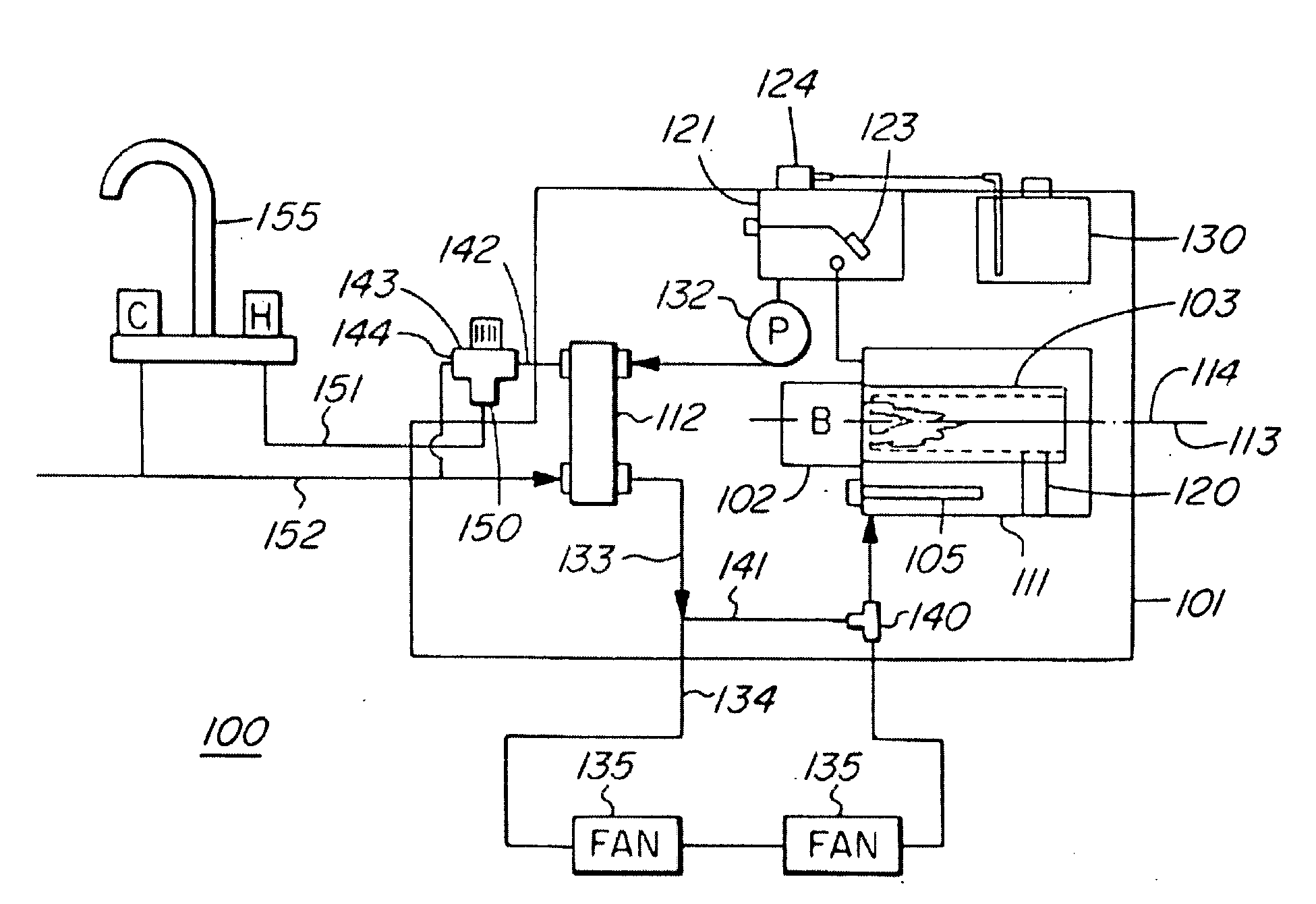
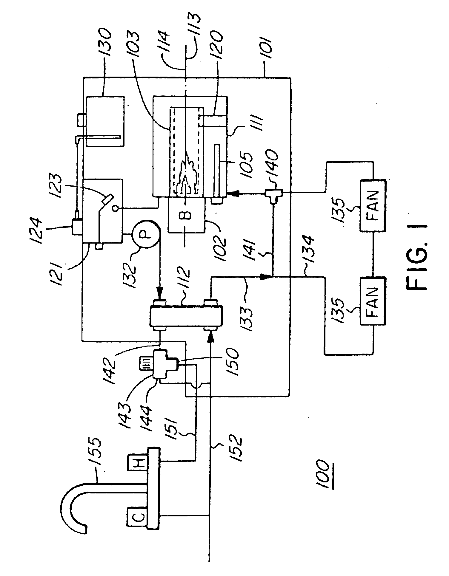
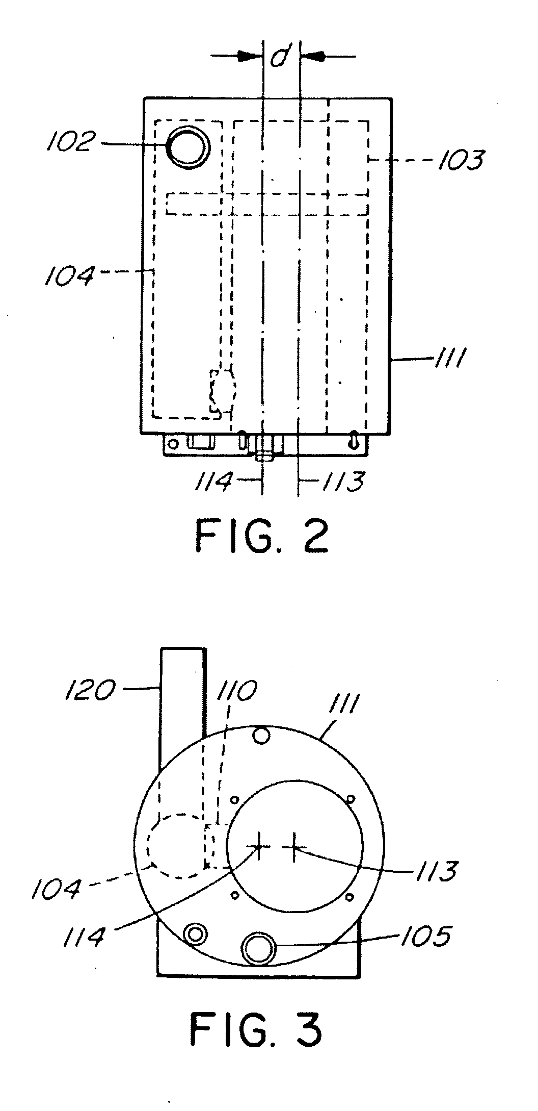
[0027]Referring now to the drawing, a coolant heater is generally illustrated at 100. It includes a heater casing 101 housing most of the components of the coolant heater 100. Such components include the burner 102, the burner tube 103 and the exhaust manifold 104 (FIG. 2 which is connected to the burner tube 103 by passageway 110 (FIG. 3). An electric element 105 is also mounted within the coolant tank 111 and is used for coolant heating when a shore connection or an RV connection is available for obtaining power. The burner tube 103, the exhaust manifold 104 and the passageway 110 are all positioned within a coolant tank 111 which contains coolant and which coolant is circulated through a heat exchanger 112 and coolant and potable water circuits under the influence of a pump 132 as will be described.

[0028]The burner tube 103 has a longitudinal axis 113 which runs generally horizontally within the heater casing 101 as best seen in FIGS. 1 and 3. The coolant tank 111 similarly has a...


PUM


Abstract

A coolant heater having a coolant tank and a burner tube within the coolant tank is used for marine and motor coach installations. The burner tube is offset sidewise from the center line of the coolant tank to allow an exhaust manifold to be positioned within the coolant tank and beside the burner tube which allows a predictable coolant movement to more evenly distribute the heat throughout the coolant. An exhaust manifold is positioned within the coolant tank in the space obtained by the burner tube offset which allows an “up” or “down” exhaust duct configuration depending on the heater installation. An expansion tank connected to the coolant tank has a level switch located within the expansion tank and a pump is operably connected to the expansion tank and to the level switch. The pump terminates operation when the level switch indicates low coolant in the expansion tank.

Description

CROSS REFERENCE TO RELATED APPLICATIONS[0001]This application claims priority from U.S. provisional patent application Ser. No. 60 / 987,772 filed Nov. 13, 2007 and entitled COMBINATION WATER AND COOLANT HEATER and from U.S. provisional patent application Ser. No. 61 / 102,727 filed Oct. 3, 2008 and entitled COOLANT AND POTABLE WATER HEATER.INTRODUCTION[0002]This invention relates to a heater and, more particularly, to a heater used primarily in recreational vehicles and boats and which allows operating components of is the heater to be contained within a single enclosure in an efficient configuration.[0003]This invention relates to a heater used for heating potable water and for space heating surroundings and, more particularly, to a heater used for such applications where the heat exchanger is combined with the burner in a single casing.BACKGROUND OF THE INVENTION[0004]Recreational vehicles, motor homes, trucks, boats and the likes particularly those of the larger variety, often have ...

Claims


Application Information

Patent Timeline
Patent Type & Authority Applications(United States)
IPC IPC(8): B60H1/00F24H1/18
CPCF24D2220/048F24H1/009F24H1/08F24H1/285F24H9/2035B60H1/00364F24D2220/0278F24D2240/10F24H1/06
Inventor RUIJVEN, EDWARD VAN
Owner INT THERMAL INVESTMENTS
Why Eureka
Try Eureka