Retaining ring structure for fixing a satellite antenna

Inactive Publication Date: 2009-07-16
SHEN WEN CHAO
View PDF14 Cites 10 Cited by
  • Summary
  • Abstract
  • Description
  • Claims
  • Application Information

AI Technical Summary

Benefits of technology

[0011]An object of the invention is to provide a retaining ring structure for fixing a satellite antenna that includes a retaining ring integrally formed by stamping a metal piece. A plurality of projecting pieces is formed at the internal side of the retaining ring for biting a positioning rod such that the retaining ring and the positioning rod are combined into one body when the positioni

Problems solved by technology

In the past, wireless communications on ground are usually affected by factors such as landforms and constructions, atmospheric layer, curvature of the earth, and electromagnetic field of the space, so that normal radio waves of communications are reflected, refracted and diffracted to give rise to poor communication effect and quality.
Moreover, the greatest drawback is that the U-shaped bolts 22 are not firmly fixed on the positioning rod 30.
That is, the connecting element 20 produces a rotation in axial direction (Y-direction) at an angle of c. In this way, the receiving dished plate 10 is no

Method used


Image

  • Retaining ring structure for fixing a satellite antenna
  • Retaining ring structure for fixing a satellite antenna
  • Retaining ring structure for fixing a satellite antenna

Examples


Example

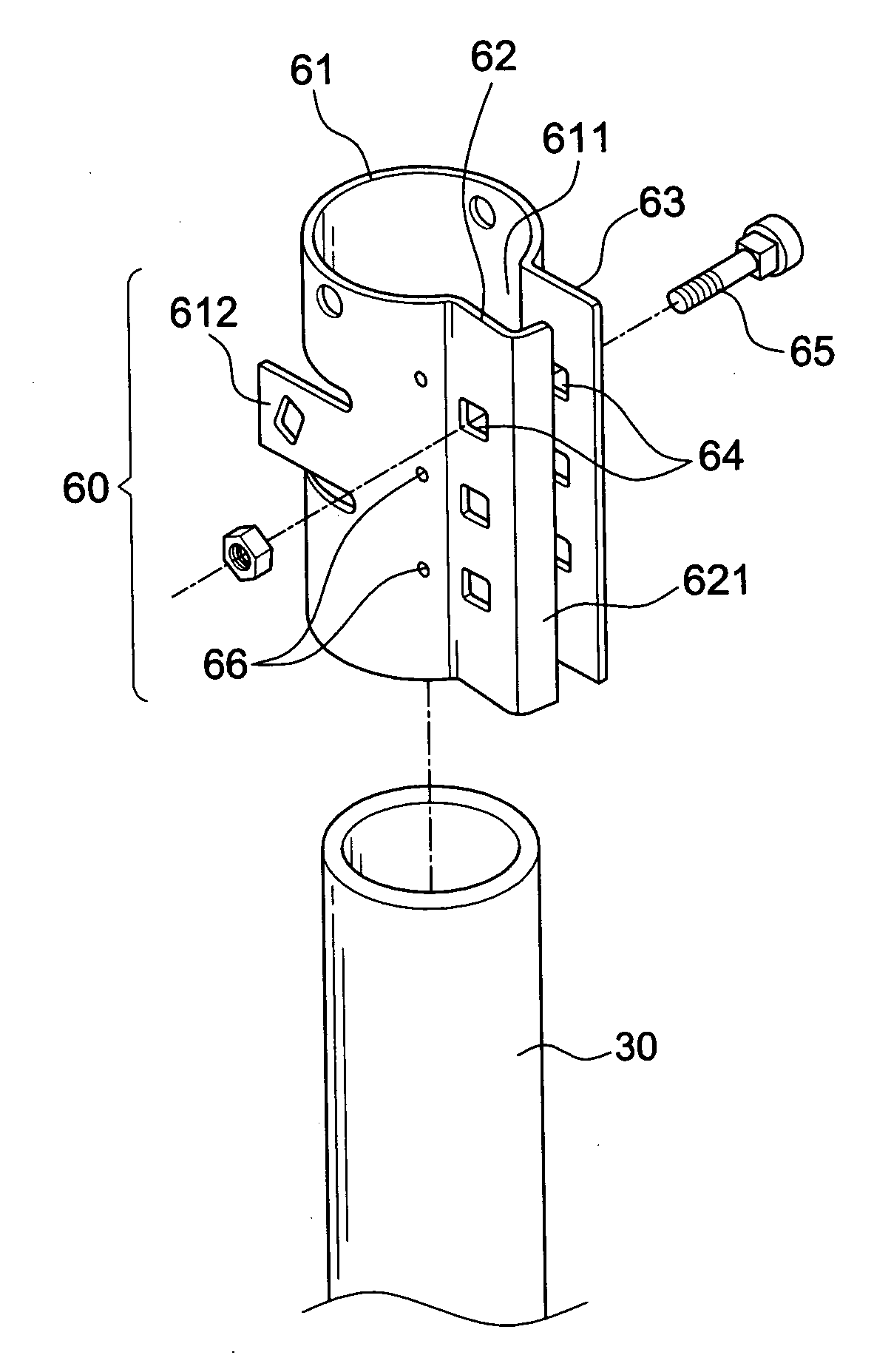
[0031]First of all, referring to FIGS. 4A through 4D, a first embodiment of the invention includes a positioning rod 30 and a retaining ring 60. The positioning rod 30 is adapted to support a receiving dished plate 10 of a satellite antenna (see FIG. 9). The positioning rod 30 is fixed either on a wall or on a base. The positioning rod 30 is necessary for the products of the invention. However, it is not the primary feature of the invention so that no further descriptions are given hereinafter. The retaining ring 60 is mounted on the positioning rod 30. The front end of the retaining ring 60 is attached to a back side 11 of the receiving dished plate 10 of a satellite antenna. In other words, the retaining ring 60 serves as a connecting element of the receiving dished plate 10.

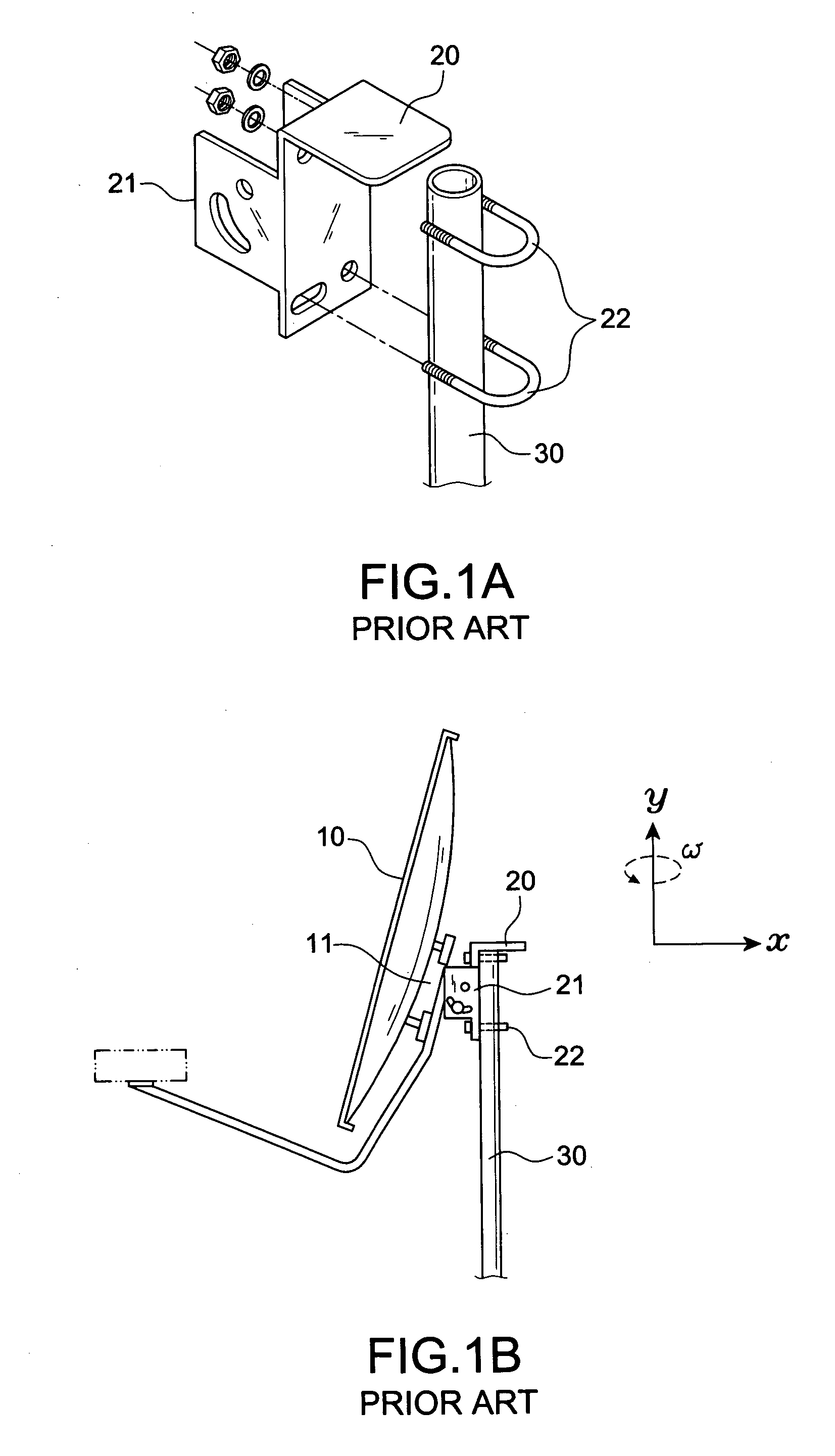
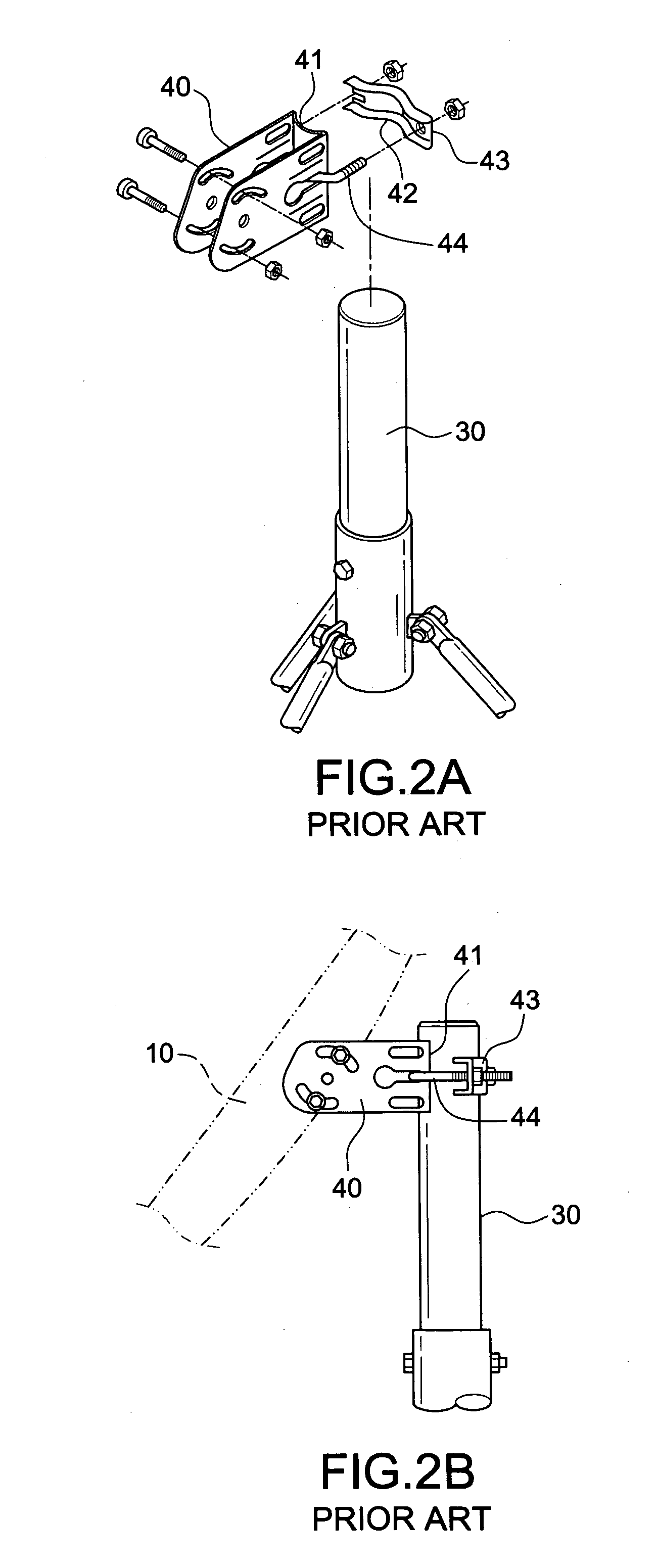
[0032]In order to eliminate the drawbacks of the conventional connecting element that easily causes rotation, the invention is characterized in that the retaining ring 60 is integrally formed by stamping a met...

Example

[0035]According to a third embodiment in FIGS. 6A and 6B, the projecting pieces 66 are formed in several rows of protruding teeth in axial direction (Y-direction) for linearly biting the positioning rod 30. It is proven by tests that both types of the above-mentioned projecting pieces 66 can be integrally formed by the stamping process on the C-shaped body 61 for firmly biting the positioning rod 30 in place.

Example

[0036]According to the second and the fourth embodiment of the invention shown in FIGS. 5 and 7, a plurality of protruding ribs 67 is horizontally arranged on the surface of the clamping pieces 62, 63 for enhancing the mechanical strength of the retaining ring 60. Furthermore, one end of the clamping piece 62 is bent inwardly in a vertical state toward the clamping piece 63 to form a restriction side 621 for keeping a proper clamping gap. Meanwhile, the restriction side 621 prevents the clamping pieces 62, 63 from over-tightening that causes an undesirable deformation.


PUM


Abstract

A retaining ring structure for fixing a satellite antenna having a retaining ring integrally formed by stamping a metal piece. The retaining ring consists of a C-shaped body and two clamping pieces extending from a slot of the C-shaped body to the outside. A plurality of projecting pieces is axially formed by a stamping process from the external side toward the internal side such that the C-shaped body is properly contracted to grip the positioning rod when the clamping pieces are tightened with bolts. Meanwhile, the projecting pieces create a biting structure that bites the positioning rod such that the positioning rod is firmly held by the retaining ring to prevent the retaining ring from rotation on the positioning rod. Moreover, the structure in accordance with the invention can withstand the inertia toque created by the strong wind force acting on the receiving dished plate. Meanwhile, the receiving dished plate won't be rotated so that an accurate direction of the receiving dished plate as well as an improved quality of receiving the satellite signals can be ensured.

Description

BACKGROUND OF THE INVENTION[0001]1. Field of the Invention[0002]The invention relates to a retaining ring structure for fixing a satellite antenna, and more particularly to a retaining ring that is integrally made by metal. Moreover, the internal side of the retaining ring includes projecting pieces for biting the positioning rod. In this way, a biting structure is created to prevent the retaining ring from rotation on the positioning rod.[0003]2. Description of the Related Art[0004]In the past, wireless communications on ground are usually affected by factors such as landforms and constructions, atmospheric layer, curvature of the earth, and electromagnetic field of the space, so that normal radio waves of communications are reflected, refracted and diffracted to give rise to poor communication effect and quality.[0005]Thereafter, a communication satellite is introduced to overcome the shortcomings of traditional wireless communications, and an earth station including a dish antenn...

Claims


Application Information

Patent Timeline
IPC IPC(8): F16L3/08
CPCF16L3/08
Inventor SHEN, WEN-CHAO
Owner SHEN WEN CHAO
Why Eureka
Try Eureka