Efficient low temperature thermal energy storage

a low temperature thermal energy and storage technology, applied in steam use, machines/engines, mechanical equipment, etc., can solve the problems of high peak load driving the capital expenditures of the electricity generation industry, lower capital costs, and higher fuel costs, so as to improve the efficiency of heat utilization in a power plant

Inactive Publication Date: 2009-07-16
AREVA SOLAR
View PDF6 Cites 144 Cited by
  • Summary
  • Abstract
  • Description
  • Claims
  • Application Information

AI Technical Summary

Benefits of technology

[0011]Also provided are a power plant and a method of retrofitting an existing power plant. Systems and methods as discussed herein may, in many instances, improve efficiency of heat utilization in a power plant.

Problems solved by technology

High peak loads drive the capital expenditures of the electricity generation industry.
Currently, the industry meets these peak loads with additional capacity, including for example, low-efficiency peaking power plants, usually gas turbines, which have lower capital costs but higher fuel costs.

Method used


Image

  • Efficient low temperature thermal energy storage
  • Efficient low temperature thermal energy storage
  • Efficient low temperature thermal energy storage

Examples


Embodiment Construction

[0014]In order to provide a more thorough understanding of the apparatus and methods described herein, the following description and calculations set forth numerous specific details, such as specific methods, parameters, examples, and the like. It should be recognized, however, that such description is not intended as a limitation on the scope of the apparatus and methods described herein, but is intended to provide a better understanding of the possible variations. Although headings are provided in the description below for convenience, the headings are not to be construed to limit the detailed description in any way.

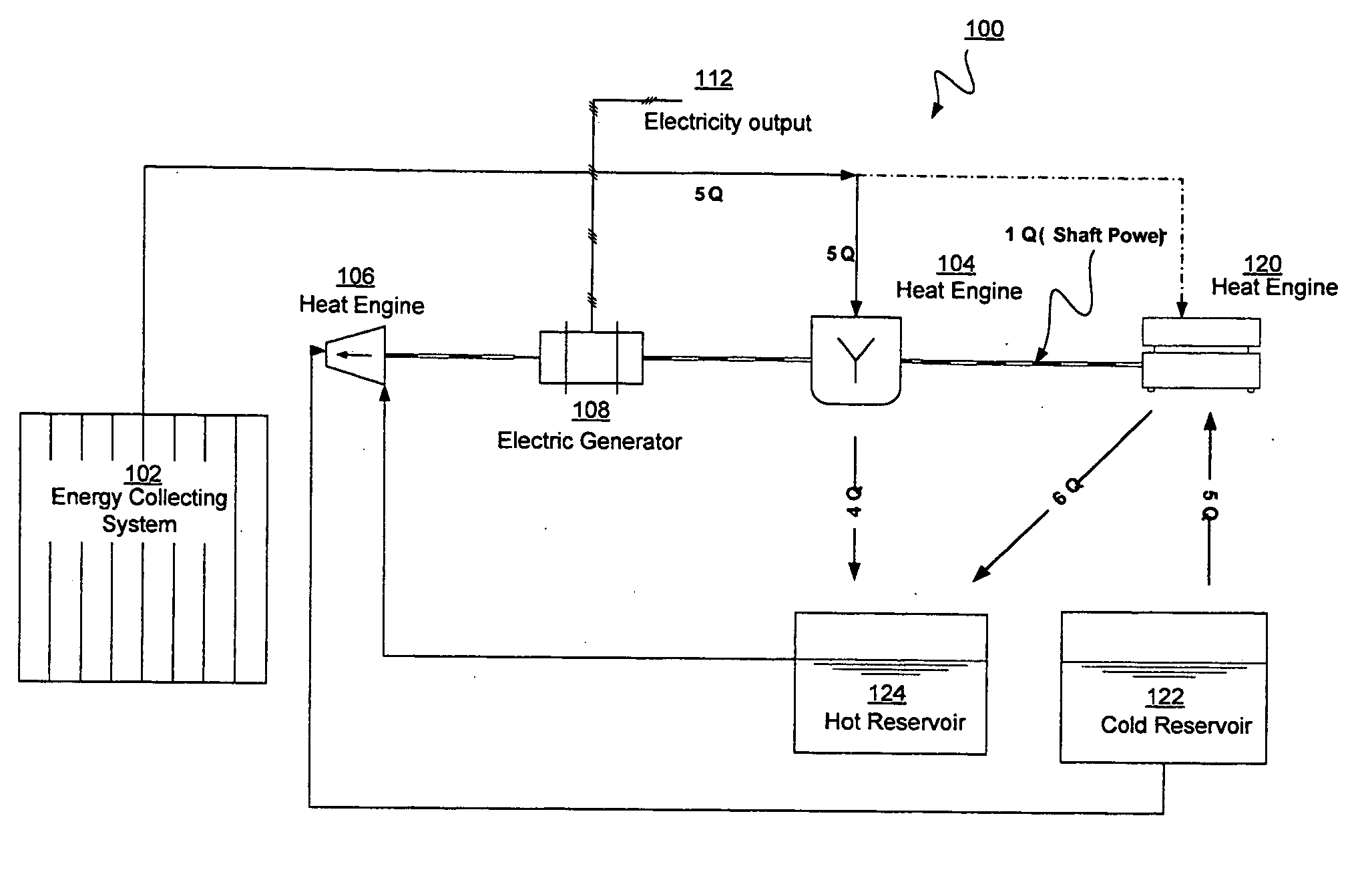
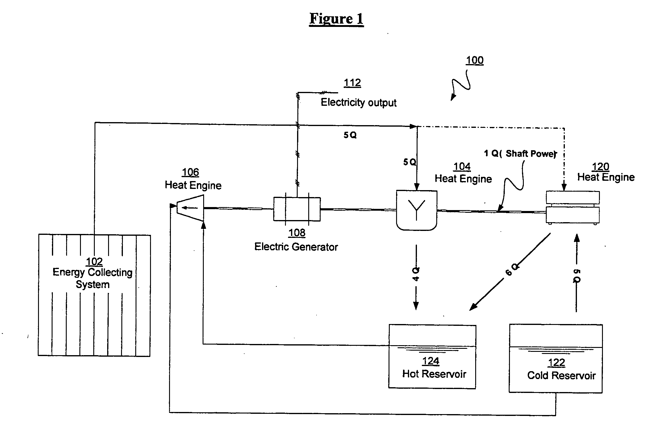
[0015]A system as described herein may be retrofitted to an existing power plant to enable the power plant to provide additional power during peak periods, for instance. A system may be incorporated into a new or existing plant to enable the plant to operate more efficiently by extracting energy from low-temperature process streams and generating electricity with that ...


PUM


Abstract

Thermal energy derived from a low temperature heat source is stored in one reservoir above ambient temperature and in another reservoir below ambient temperature for use in driving an organic Rankine cycle engine to produce electricity. The organic Rankine cycle engine may utilize an organic working fluid that boils below or near ambient temperature. Solar energy may be used to power a heat pump or chiller that provides the hot and cold storage fluids stored in hot and cold reservoirs for use in the organic Rankine cycle engine.

Description

RELATED APPLICATIONS[0001]This application claims the benefit of priority to U.S. application Ser. No. 60 / 986,978 filed Nov. 9, 2007 and entitled “Thermal Energy Storage Through the Use of Mechanically Driven Chillers and Insulated Water Holding Tanks,” inventors E. Ellis and M. Venetos, the contents of which are incorporated by reference in their entirety herein as if put forth in full below.FIELD[0002]The apparatus and methods described herein concern the storage of low temperature thermal energy and the efficient conversion of such stored thermal energy to generate electricity.BACKGROUND[0003]High peak loads drive the capital expenditures of the electricity generation industry. Currently, the industry meets these peak loads with additional capacity, including for example, low-efficiency peaking power plants, usually gas turbines, which have lower capital costs but higher fuel costs. As an alternative to adding additional capacity during peak loads, energy storage has great potent...

Claims


Application Information

Patent Timeline
Patent Type & Authority Applications(United States)
IPC IPC(8): F02B63/04F03G6/06F01K25/00F03G7/10
CPCF01K3/12F01K9/003F01K25/10F03G6/005F03G6/067F01K23/10Y02T10/16Y02T10/166F01K13/02F01K17/005F01K17/04Y02E10/46Y02T10/12
Inventor ELLIS, ERIKVENETOS, MILTON
Owner AREVA SOLAR
Why Eureka
Try Eureka