Air Drag Reduction Apparatus for Tractor-Trailers

a technology for reducing apparatus and tractor trailers, which is applied in the direction of roofs, transportation and packaging, vehicle arrangements, etc., can solve the problems of the top panel moving downward, and achieve the effects of reducing their effectiveness, preventing impact damage, and increasing the cost of operation

Inactive Publication Date: 2009-07-16
HOLUBAR ROBERT
View PDF3 Cites 91 Cited by
  • Summary
  • Abstract
  • Description
  • Claims
  • Application Information

AI Technical Summary

Benefits of technology

[0016]In another desirable form of the invention, a wheel may be provided at a lower outer corner of a side panel in a position such that direct contact between the panel and an external structure may be minimized and/or avoided. Such wheel may be utilized to cause the panels to collapse when an external pressure is applied thereto.
[0017]The present invention as thus described provides a significant advantage over other aerodynamic enhancing prior art devices. Specifically, the most significant problem encountered with aerodynamic panels mounted on tractor-trailer units is that the panels are prone to receive accidental non-ballistic impacts which damage the panels, due to the outwardly extending configuration of the panels, thus reducing their effectiveness and eventually requiring repair or replacement of the panels. This significantly increases th

Problems solved by technology

Moreover, an inward movement of the associated side panel caused by contact with an external structure, or ot

Method used


Image

  • Air Drag Reduction Apparatus for Tractor-Trailers
  • Air Drag Reduction Apparatus for Tractor-Trailers
  • Air Drag Reduction Apparatus for Tractor-Trailers

Examples


Embodiment Construction

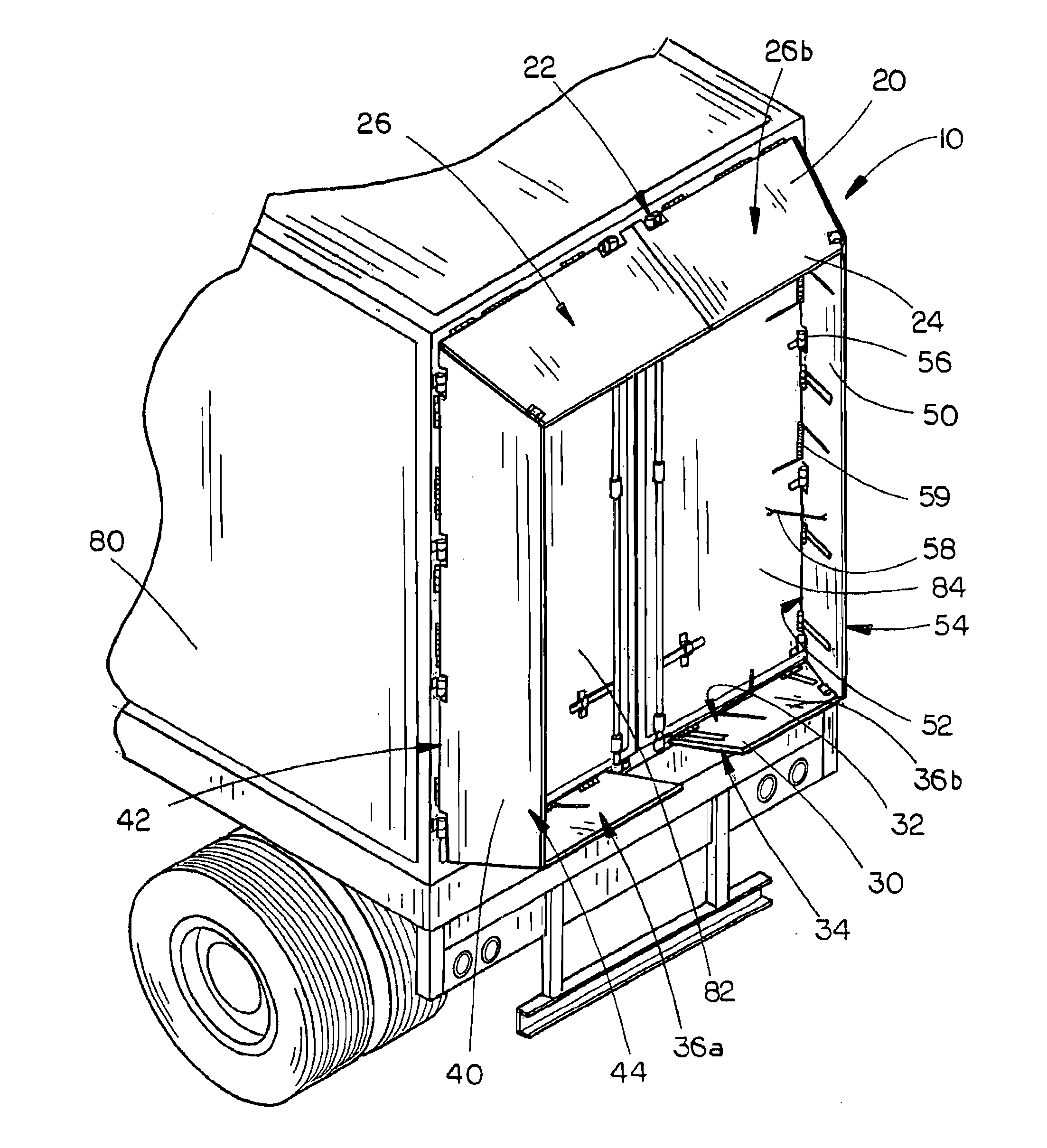
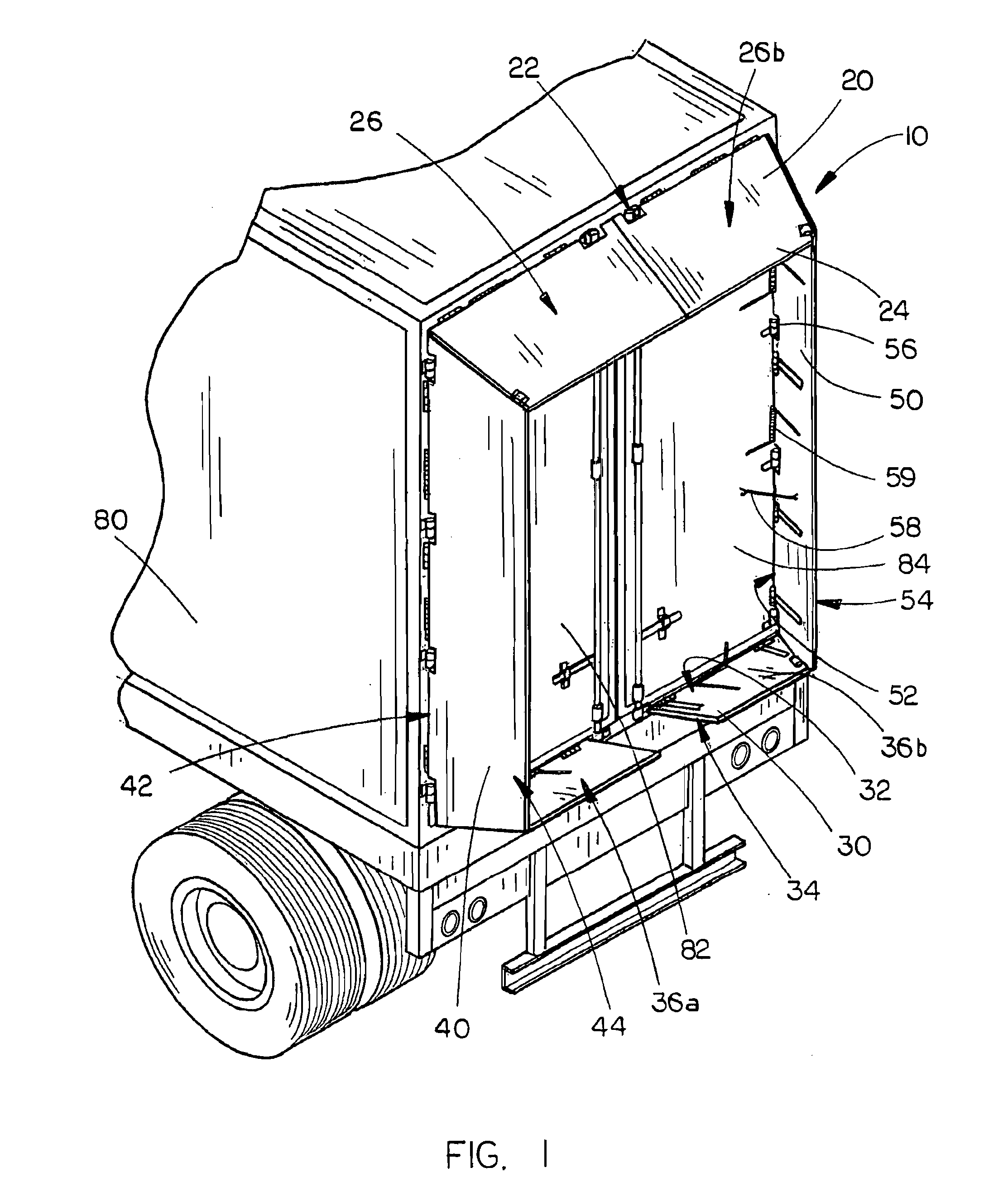
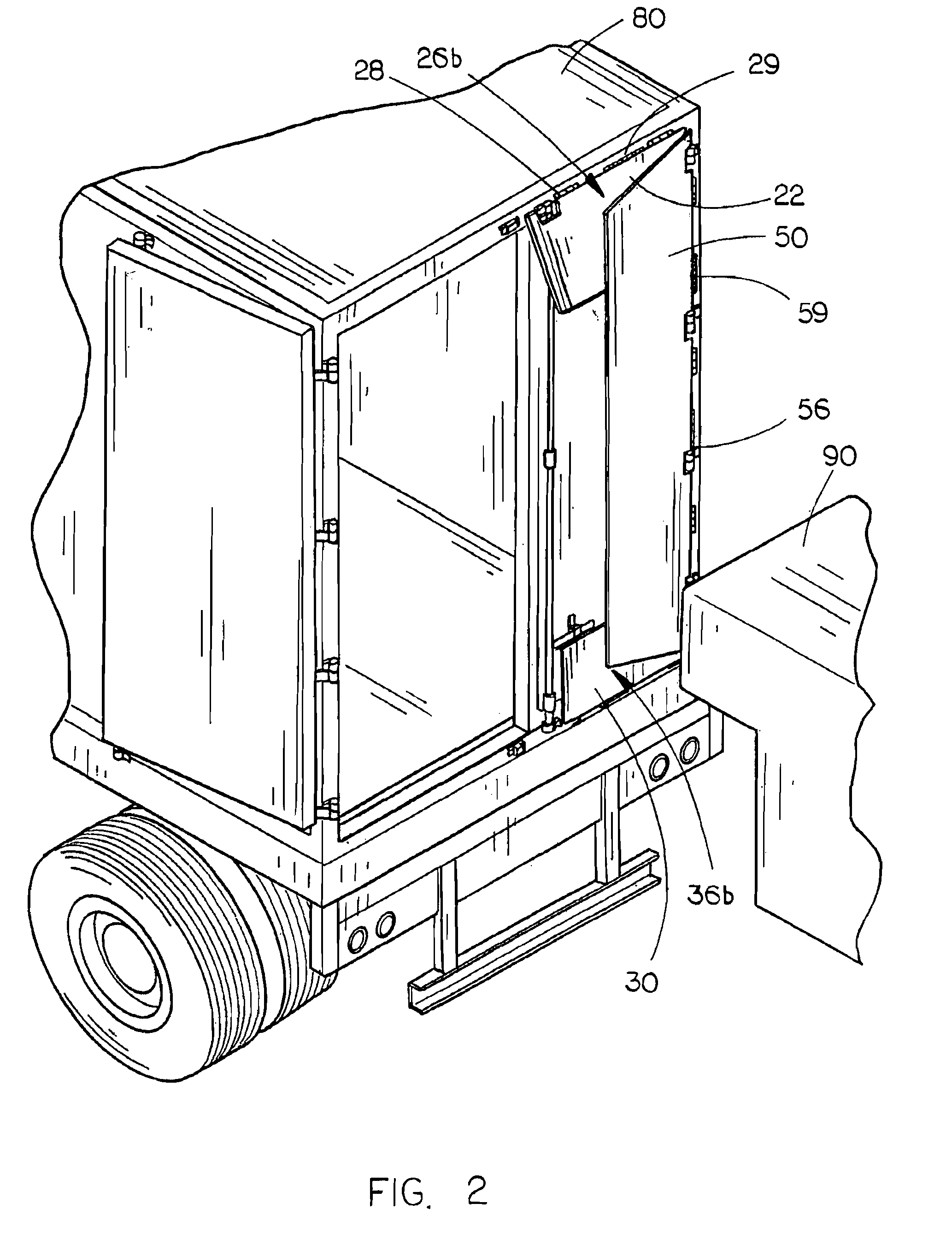
[0035]The air drag reduction apparatus 10 of the present invention is shown best in FIGS. 1-4 as including four aerodynamic panels, specifically a top panel 20, bottom panel 30, left side panel 40, and right side panel 50. It is preferred that each of the panels has the same generally trapezoidal shape, with the inner edges 22, 32, 42, 52 of the panels each having a greater length than the respective outer edges 24, 34, 44, 54 of the panels. In a preferred embodiment, each of the panels, 20, 30, 40, 50 may be constructed of a sturdy plastic or metal sheet material, although it has been found that the use of plastic material will significantly decrease the weight of the panels 20, 30, 40, 50 while simultaneously not sacrificing durability and effectiveness. Of course, however, the precise nature of the construction materials used in connection with the panels 20, 30, 40, 50 is not critical to the present invention so long as the aerodynamic enhancing features of the present invention...


PUM


Abstract

An air drag reduction apparatus includes left and right panels and top and bottom panels for mounting to the rear doors of a tractor trailer along the top, bottom and side edges thereof. Hinges are interposed between the panels and the doors so that the panels can pivot about the hinges between an extended drag-reducing position and a collapsed position generally adjacent the rear doors. Stop devices releasably secure the panels in the extended position, and biasing devices such as tensioning springs are operative to bias the panels outwardly and rearwardly to the extended position and are further operative to permit the panels to pivot between the extended position towards and to the collapsed position upon impact and contact from an external object occurring and then return to the extended position substantially immediately upon contact ceasing thereby significantly reducing the impact damage. The apparatus also includes a ramp and wheel arrangement to facilitate opening and collapsing of the panels. The apparatus of the invention also includes an outwardly extending panel protection member projecting from the lower corner of the panel in a position for being contacted by external objects during movement of the vehicle to thereby prevent direct contact between an external object and the panel and cause the panel to move toward its collapsed position

Description

CROSS REFERENCE TO RELATED APPLICATION[0001]This application is a continuation-in-part of U.S. patent application Ser. No. 11 / 827,721 filed on Jul. 13, 2007, which in turn is a continuation-in-part of U.S. patent application Ser. No. 11 / 508,795 filed on Aug. 23, 2006. Priority is claimed herein from each of said prior applications pursuant to 35 U.S.C. § 120. Moreover, the entireties of the disclosures of said prior applications are hereby incorporated herein by reference.BACKGROUND OF THE INVENTION[0002]1. Field of the Invention[0003]The present invention is directed to air drag reduction devices for vehicles and, more particularly, to air drag reduction apparatus for tractor-trailers which includes left, right and top panels, and in some cases lower, panels, which panels are mounted by hinges on the generally rectangular rear doors of the tractor-trailer and are swingable into an extended drag-reducing position where they are disposed at an inward angle of approximately five to tw...

Claims


Application Information

Patent Timeline
IPC IPC(8): B62D35/00
CPCB62D35/001
Inventor HOLUBAR, ROBERT
Owner HOLUBAR ROBERT
Why Eureka
Try Eureka