Area and power efficient architectures of time deinterleaver for isdb-t receivers

a time deinterleaver and receiver technology, applied in the field of communication systems, can solve problems such as large number of counters, data gets distorted by channel impairments, and transmission data typically cannot be completely recovered

Active Publication Date: 2009-07-16
ATMEL CORP
View PDF2 Cites 32 Cited by
  • Summary
  • Abstract
  • Description
  • Claims
  • Application Information

AI Technical Summary

Benefits of technology

[0006]In view of the foregoing, an embodiment herein provides an apparatus for de-interleaving interleaved data in an OFDM based ISDB-T receiver comprising of a deinterleaver memory; a OFDM symbol counter incrementing once for each OFDM symbol, wherein a practical bit width of the OFDM symbol counter is in the range of 25 bits (less conservative) to 30 bits (more conservative); a divider for calculating intra buffer offset in the deinterleaver memory for every increment of the OFD

Problems solved by technology

In various communication systems, data gets distorted by channel impairments like fading, multipath prorogations, interference, Doppler Effect, etc.
In case of small errors the altered bits can be corrected easily by using error correction codes, but in case of burst errors, higher numbers of data bits are altered an

Method used


Image

  • Area and power efficient architectures of time deinterleaver for isdb-t receivers
  • Area and power efficient architectures of time deinterleaver for isdb-t receivers
  • Area and power efficient architectures of time deinterleaver for isdb-t receivers

Examples


first embodiment

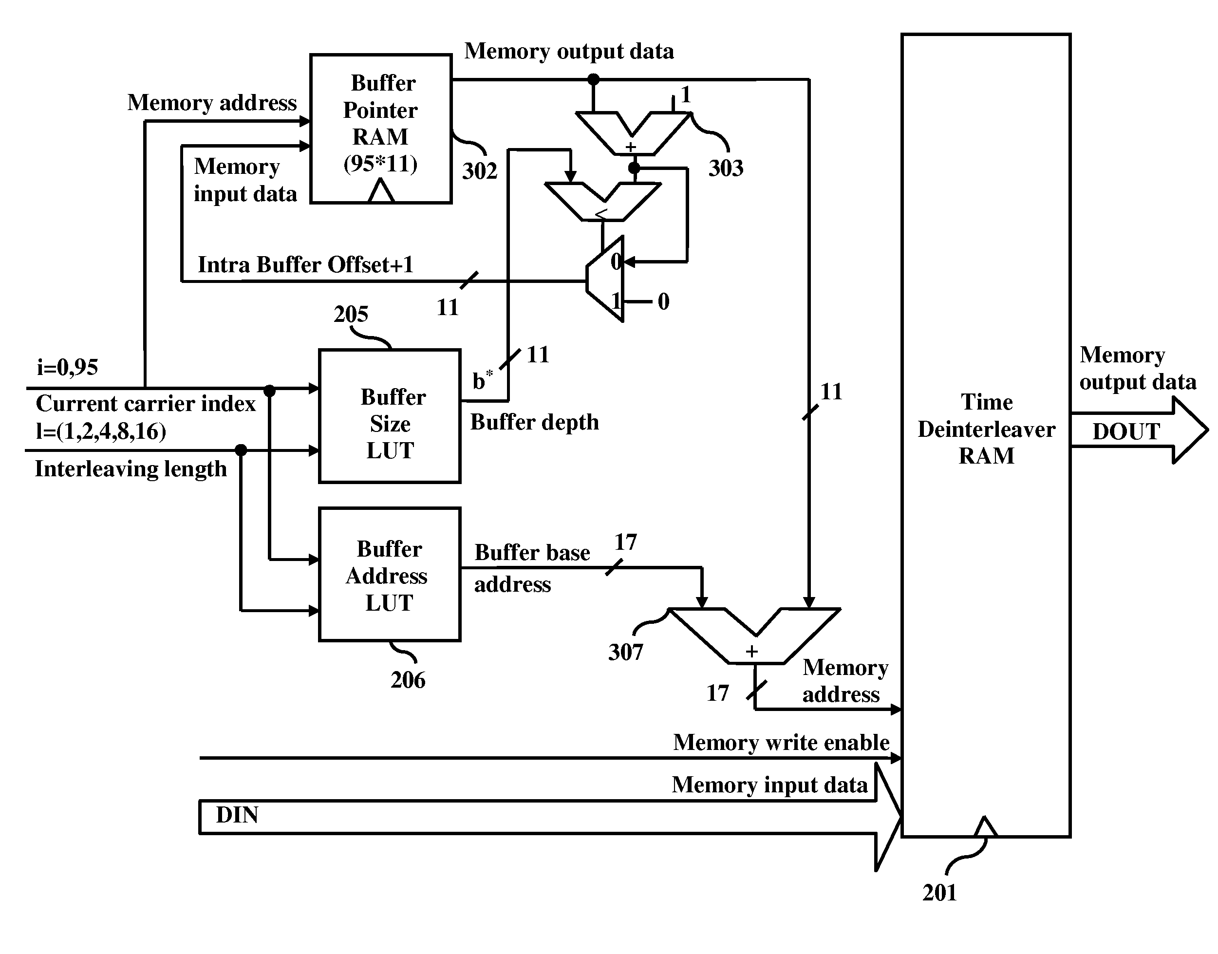
[0035]FIG. 4, with reference to FIGS. 1 and 2, illustrates a method for de-interleaving interleaved data using memory based pointer architecture in accordance with the first embodiment herein. The method begins at step 410, where for each data carrier the corresponding pointer value is read from the buffer pointer RAM 302 and incremented using adder 303. The incremented value is stored back in the buffer pointer RAM 302. At step 420 the delay buffer size value of the corresponding carrier is retrieved from the first LUT 205. The incremented pointer value is compared with the retrieved buffer size value using circular increment logic to calculate the intra buffer offset at step 430. Circular increment logic involves adding ‘1’ to the incremented pointer value and comparing the new pointer value with the retrieved buffer size value. If the new value exceeds the buffer size, the new pointer value is zeroed out. At step 440, the buffer base address value of the corresponding carrier is ...

second embodiment

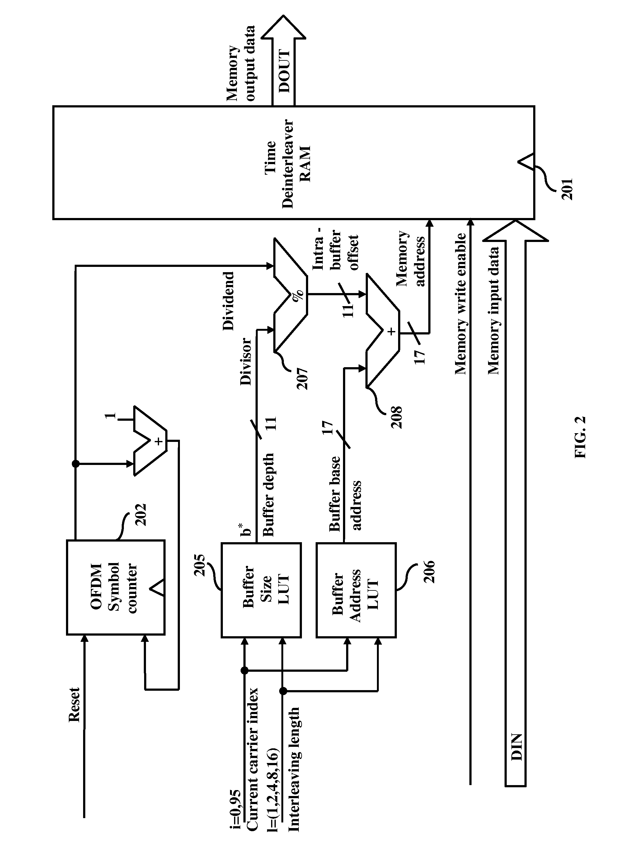
[0036]FIG. 5, with reference to FIGS. 1 and 3, illustrates a method for de-interleaving interleaved data using modulo based pointer architecture in accordance with the second embodiment herein. The method begins at step 510, where OFDM symbol counter 202 counts each received symbol. At step 520 the delay buffer size value of the corresponding carrier is retrieved from the first LUT 205. The intra buffer offset is calculated by dividing the OFDM symbol counter with retrieved delay buffer size value at step 530 using modulo divider 207. At step 540, the buffer base address value of the corresponding carrier is retrieved from the second LUT 206. The memory address where the input data needs to be stored is calculated by adding the intra buffer offset to the retrieved buffer base address at step 550. The data bits get stored in the deinterleaver RAM 201 at step 560.

[0037]FIG. 6 illustrates the test data input timing for both the modulo based pointer architecture of FIG. 2 and the memory...


PUM


Abstract

A method and apparatus for de-interleaving interleaved data in a deinterleaver memory in an Orthogonal Frequency Division Multiplexing (OFDM) based Integrated Services Digital Broadcasting Terrestrial (ISDB-T) receiver. In different embodiments, the apparatus comprises of a OFDM symbol counter along with a divider or a buffer pointer RAM with circular pointer logic, a first lookup table to obtain delay buffer size and interleaving lengths for a given OFDM transmission layer, and a second lookup table to obtain buffer base address and interleaving lengths for a given OFDM transmission layer.

Description

BACKGROUND[0001]1. Technical Field[0002]The embodiments herein generally relate to communication systems, and more particularly to the field of de-interleaving interleaved data in orthogonal frequency division multiplexing (OFDM) communication systems, such as integrated services digital broadcasting terrestrial (ISDB-T) systems.[0003]2. Description of the Related Art[0004]In various communication systems, data gets distorted by channel impairments like fading, multipath prorogations, interference, Doppler Effect, etc. In case of small errors the altered bits can be corrected easily by using error correction codes, but in case of burst errors, higher numbers of data bits are altered and the transmitted data typically cannot be recovered completely. Time interleaving is performed by spreading coded symbols in time before transmission to protect data from burst errors.[0005]OFDM based communication systems, such as ISDB-T use time interleaving to randomize modulated symbol data in the...

Claims


Application Information

Patent Timeline
IPC IPC(8): H04N5/455
CPCH03M13/2732H03M13/276H04L27/2647H04L1/0052H04L1/0071H03M13/2789
Inventor TREIGHERMAN, PHILIP
Owner ATMEL CORP
Why Eureka
Try Eureka