Microscope apparatus and focal-depth enlarged image generation method used therefor
a microscope and enlarged image technology, applied in the field of microscope apparatus and focal-depth enlarged image generation method used therefor, can solve the problems of degraded s/n ratio in the addition image and blurred imag
- Summary
- Abstract
- Description
- Claims
- Application Information
AI Technical Summary
Benefits of technology
Problems solved by technology
Method used
Image

Examples
first embodiment
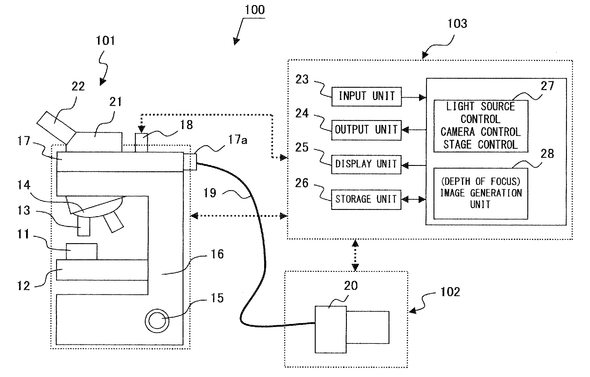
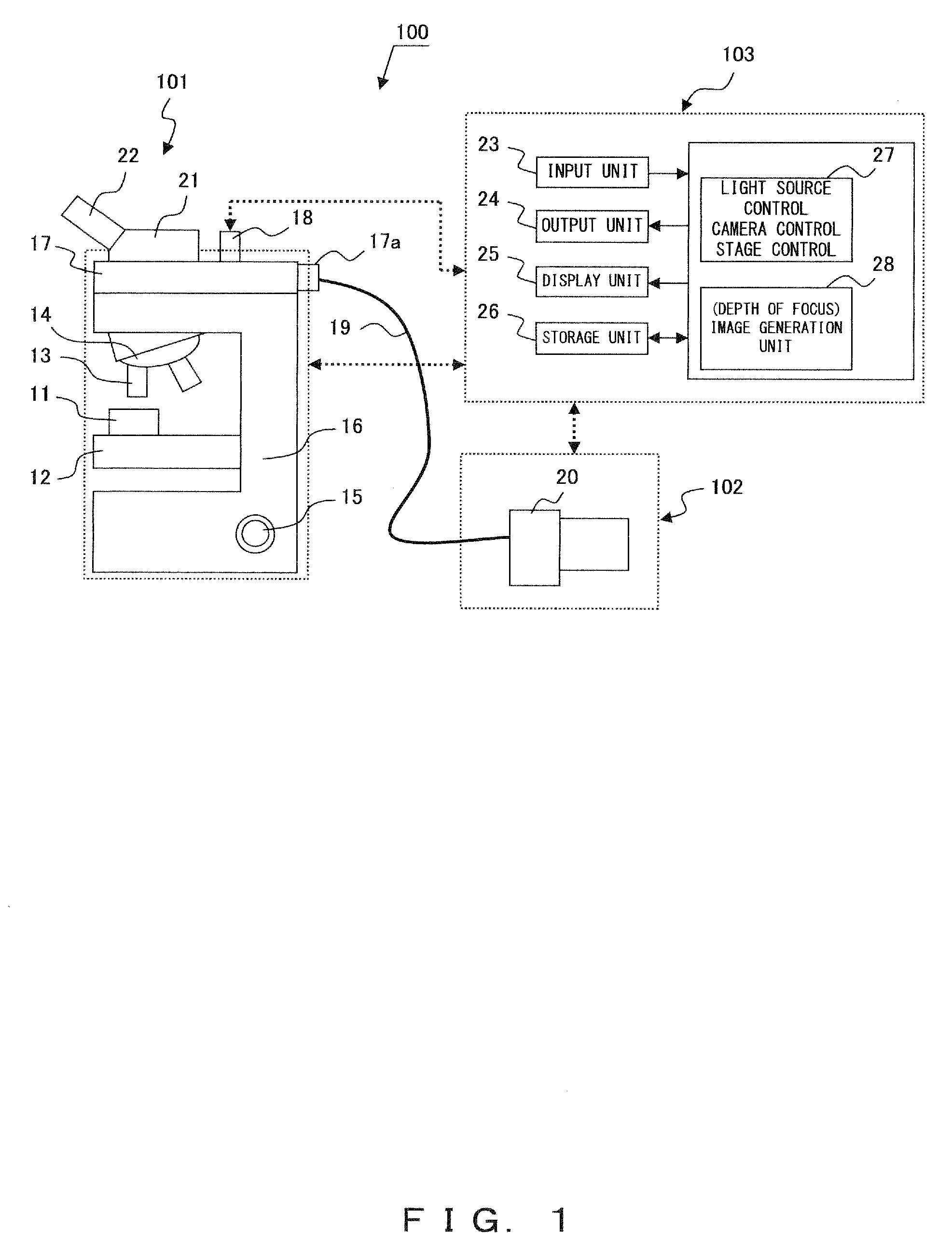
[0045]FIG. 3 is a diagram showing an exemplary setup screen for the setting of the import region of a focal-depth enlarged region and the import condition in the microscope apparatus 100 according to the The setup screen is displayed in the display unit 25 under the control of the control unit 27.
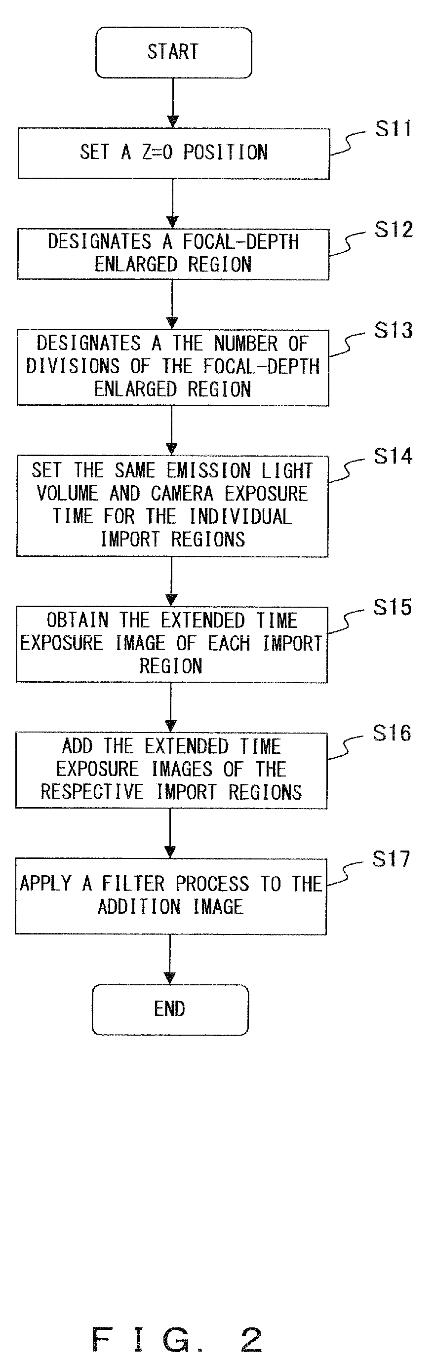
[0046]The user of the microscope apparatus 100 designates the distance of a focal-depth enlarged region from the reference position (at Z=0) in the positive and negative directions in the Z axis direction and from the number of divisions of the focal-depth enlarged region.
[0047]FIG. 3 exemplifies the case of designating “±2000 nm” as the distance of a focal-depth enlarged region and “8” as the number of divisions of the focal-depth enlarged region.
[0048]When the distance of the focal-depth enlarged region in the Z axis direction and the number of divisions “8” are designated, the control unit 27 divides the range +2000 nm to −2000 nm into eight import regions and calculates the start posit...
second embodiment
[0057]Next is a description of a second preferred embodiment of the present invention. The second embodiment is configured to designate the optimal exposure time and emission light volume of a light source in the middle position of each import region.
[0058]FIG. 5 is a diagram showing an exemplary GUI screen for designating import regions and import conditions according to the second embodiment.
[0059]FIG. 5 exemplifies the case of designating “±2000 nm” as the size of a focal-depth enlarged region and “8” as the number of divisions. When the size of a focal-depth enlarged region and the number of divisions are designated, the control unit 27 calculates the start position and end position of each import region, calculates “−2000” as the start position of the first import region, “−1500” as the end position thereof, “−1500” as the start position of the second import region, “−1000” as the end position thereof, and so on, and displays the calculated numbers as the start position and end...
third embodiment
[0064]Next is a description of a third preferred embodiment of the present invention. The third embodiment is configured to correct the extended time exposure image of each import region with a weighting factor when the exposure time for each import region and the emission light volume of a light source are discretionarily designated.
[0065]Here, where “PStart [i] is defined as the start position of the designated i-th import region, “PEnd[i]” as the end position, “L[i]” as the emission light volume of the light source for the i-th import region, and “E[i]” as the exposure time in the above described setup screen, a value “k” is calculated as follows:
k[i]=|PEnd[i]−PStart[i]| / (L[i]*E[i])
[0066]Then, with the value k of the j-th import region used as a reference, the values k of other import regions is normalized to calculate a weighting factor. Where “1” is the weighting factor sk[j] of the j-th import region, the weighting factor sk[i] of the i-th import region is expressed by the fol...
PUM
 Abstract
Description
Claims
Application Information
 - R&D
- Intellectual Property
- Life Sciences
- Materials
- Tech Scout
- Unparalleled Data Quality
- Higher Quality Content
- 60% Fewer Hallucinations
Browse by: Latest US Patents, China's latest patents, Technical Efficacy Thesaurus, Application Domain, Technology Topic, Popular Technical Reports.
© 2025 PatSnap. All rights reserved.Legal|Privacy policy|Modern Slavery Act Transparency Statement|Sitemap|About US| Contact US: help@patsnap.com