Electric Device Having a Plastic Plug Part Arranged on a Circuit Support

a technology of electric devices and circuit supports, which is applied in the direction of electrical devices, electrical discharge lamps, coupling device connections, etc., can solve the problems of high acceleration forces during operation, severe affecting the reliability of electronic and harsh ambient conditions of electric devices employed in motor vehicles. , to achieve the effect of simple implementation and economical production

Inactive Publication Date: 2009-07-16
MELECS EWS GMBH & CO KG
View PDF8 Cites 16 Cited by
  • Summary
  • Abstract
  • Description
  • Claims
  • Application Information

AI Technical Summary

Benefits of technology

[0007]The object of the invention is to provide an electric device in the case of which the mechanical fastening between a plastic plug part

Problems solved by technology

Electric devices employed in a motor vehicle are exposed to harsh ambient conditions.
High acceleration forces can occur during operation.
Even slight alternating stresses on said solder connections can severely affect the electronic device's reliability.
However, the problem therein arises that if the plastic plug part is arranged on a side of the circuit support facing away from the housing baseplate then the plastic plug part will not be able to take up the mechanical forces necessary for producing the rivet joint without being dam

Method used


Image

  • Electric Device Having a Plastic Plug Part Arranged on a Circuit Support
  • Electric Device Having a Plastic Plug Part Arranged on a Circuit Support
  • Electric Device Having a Plastic Plug Part Arranged on a Circuit Support

Examples


Embodiment Construction

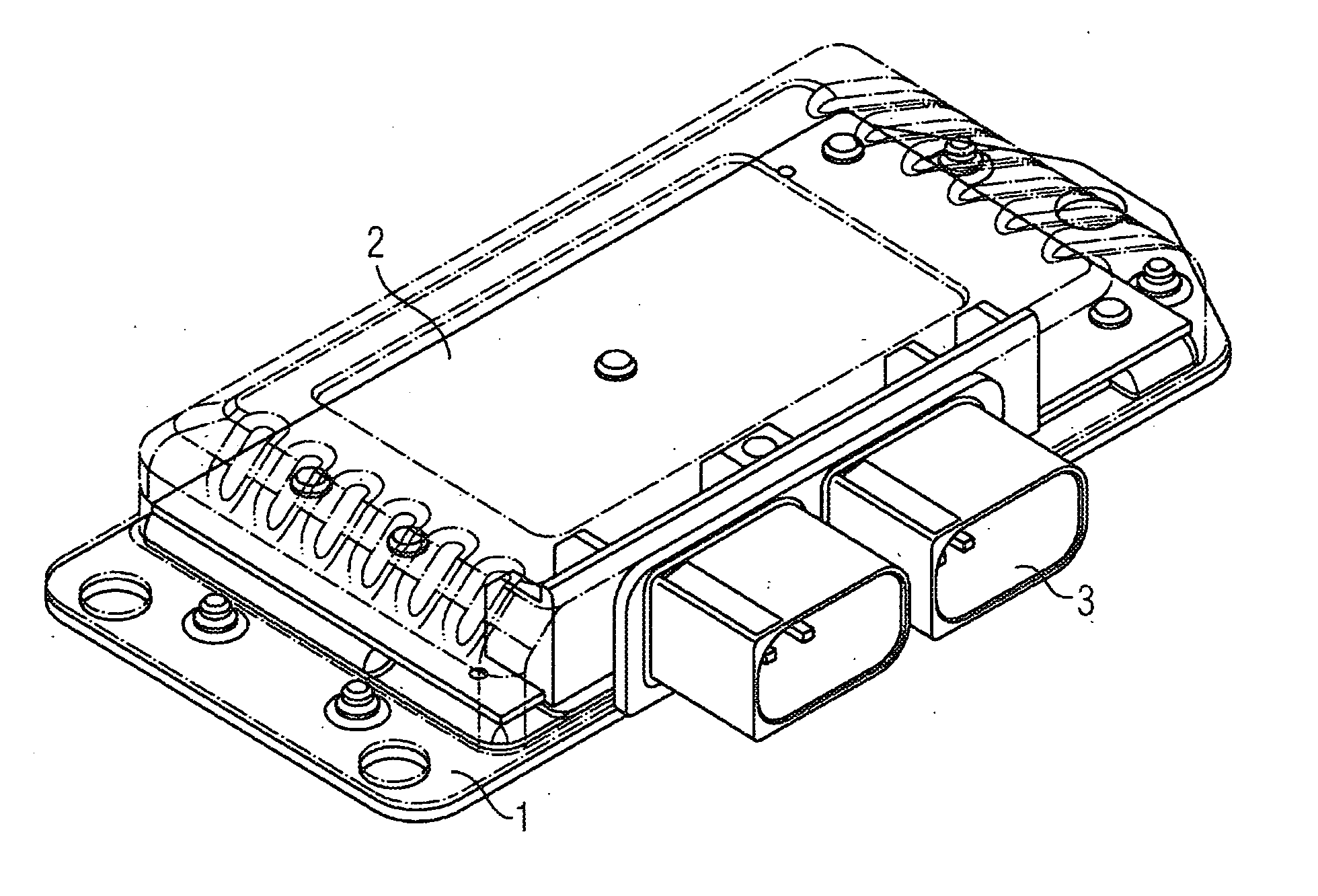
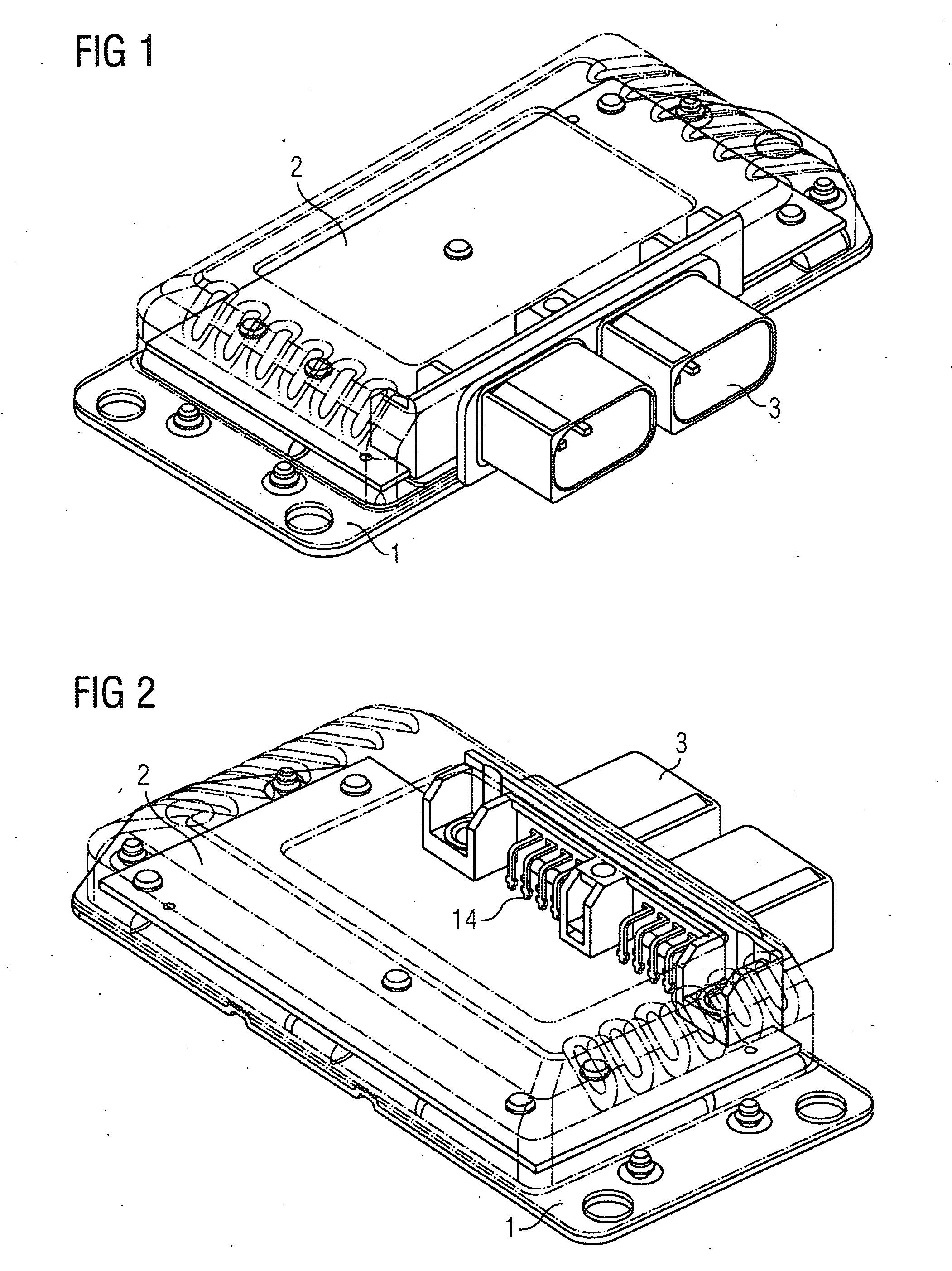
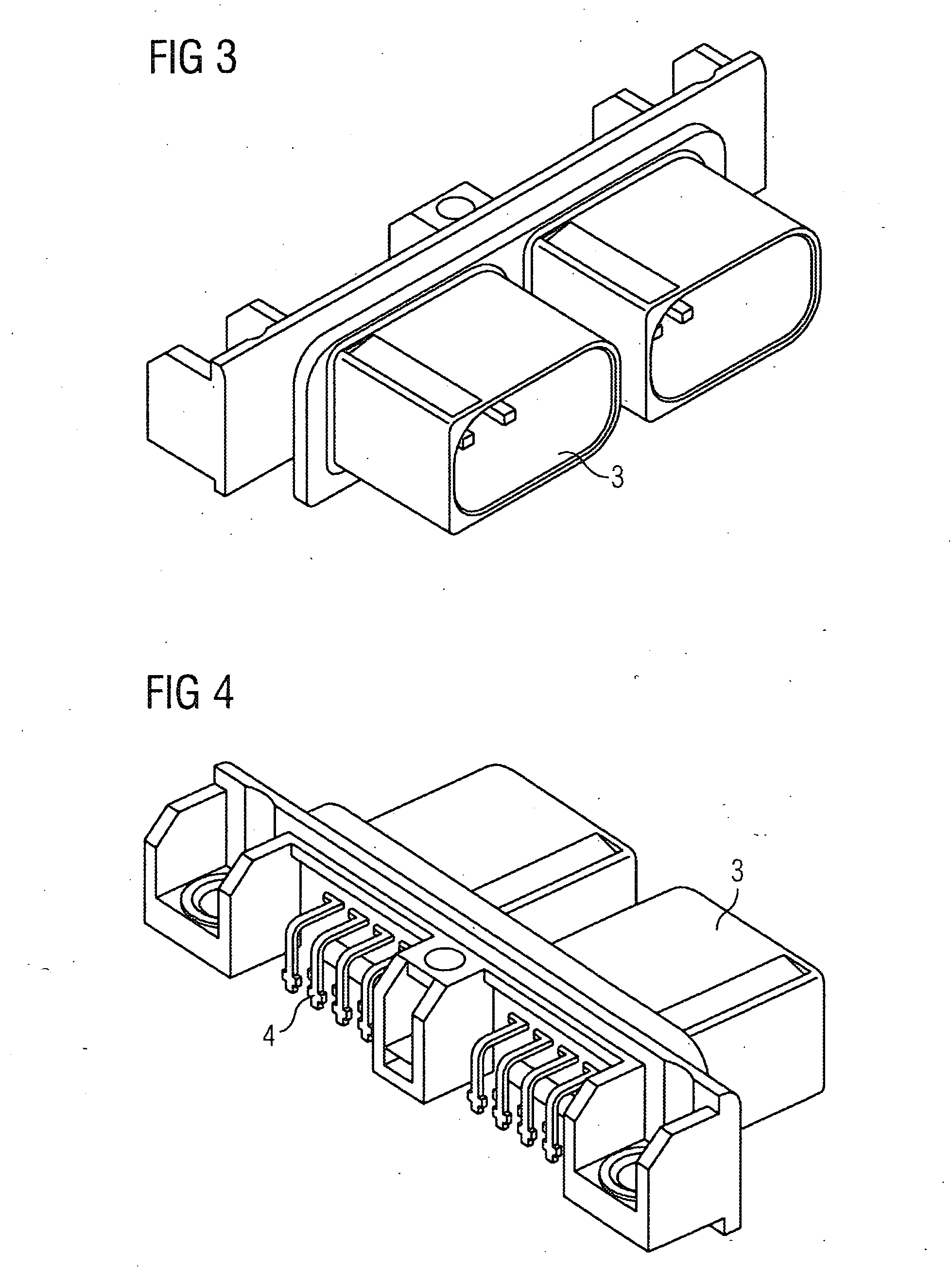
[0024]FIGS. 1 and 2 show in each case as an exemplary embodiment of the invention a perspective view of a control device for a motor vehicle. Fastened onto a flat housing baseplate 1 is a circuit support 2 that can be seen through the transparently shown housing cover. Fastened onto the circuit support 2 is a plastic plug part 3 that is shown in FIG. 3 with a view onto the plug shaft. FIG. 4 shows the plastic plug part 3 with a view onto the pc-board plug-in contacts 4. The pc-board plug-in contacts 4 establish the electric connection to printed conductors 14 on the circuit support 2.

[0025]FIGS. 5a and 5b show in a sectional drawing by way of example the fastening between the plastic plug part 3, circuit support 2, and housing baseplate 1. Hollow cylindrical, thin-walled rivet pegs 8 have been formed on the housing baseplate 1 through extrusion. Said rivet pegs 8 form—as explained in more detail below—a mechanical connection between the plastic housing part 3, circuit support 2, and...


PUM


Abstract

Disclosed is an electrical device, in particular a control unit for a motor vehicle, comprising a plate-shaped circuit support fixed on a metallic base plate of the housing, on which a plastic plug part s fixed on a side facing away from the metallic base plate, characterized in that fixing means which are pivot-shaped and protrude from the base plate, are provided for the common mounting of the plastic plug part, the circuit support and the metallic base plate of the housing, that said fixing means are guided through corresponding recesses in the circuit support and in the plastic plug part, that a deformation is produced at each inserted end and that each deformation is supported y a supporting part on said plastic plug part.

Description

CROSS REFERENCE TO RELATED APPLICATIONS[0001]This application is the US National Stage of International Application No. PCT / EP2007 / 050207 filed Jan. 10, 2007 and claims the benefit thereof. The International Application claims the benefits of Austrian application No. 355 / 2006 filed Mar. 2, 2006, both of the applications are incorporated by reference herein in their entirety.FIELD OF INVENTION[0002]The invention relates to an electric device, in particular a control device for a motor vehicle, having a plate-shaped circuit support that is fastened to a metallic housing baseplate and on which on a side facing away from the housing baseplate is arranged a plastic plug part.BACKGROUND OF THE INVENTION[0003]Electric devices employed in motor-vehicle engineering for example for controlling a gear consist mostly of a plate-shaped circuit support accommodated in a housing and fastened to a housing baseplate. A cable is connected via a plastic plug part led through a duct in the housing. The...

Claims


Application Information

Patent Timeline
IPC IPC(8): H05K5/00
CPCH05K5/006H01R12/724H05K5/0069H05K5/0082
Inventor CHLUMSKY, LUBOMIRHELLINGER, LEOPOLDKOCEVAR, ANTONNEUMANN, GERHARD
Owner MELECS EWS GMBH & CO KG
Why Eureka
Try Eureka