Fan and bearing structure
a technology of bearing structure and fan, which is applied in the field of bearing structure of the fan, can solve the problems of non-uniform stress induced by the element, abrasion becomes serious, and the fan size variation caused by the engagement is reduced, and the shaft can rotate smoothly. , to achieve the effect of discharging the heat generated by the fan during the operation and reducing the size variation of the fan
- Summary
- Abstract
- Description
- Claims
- Application Information
AI Technical Summary
Benefits of technology
Problems solved by technology
Method used
Image
Examples
first embodiment
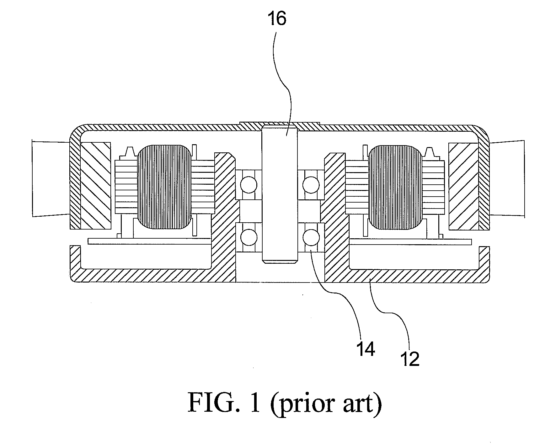
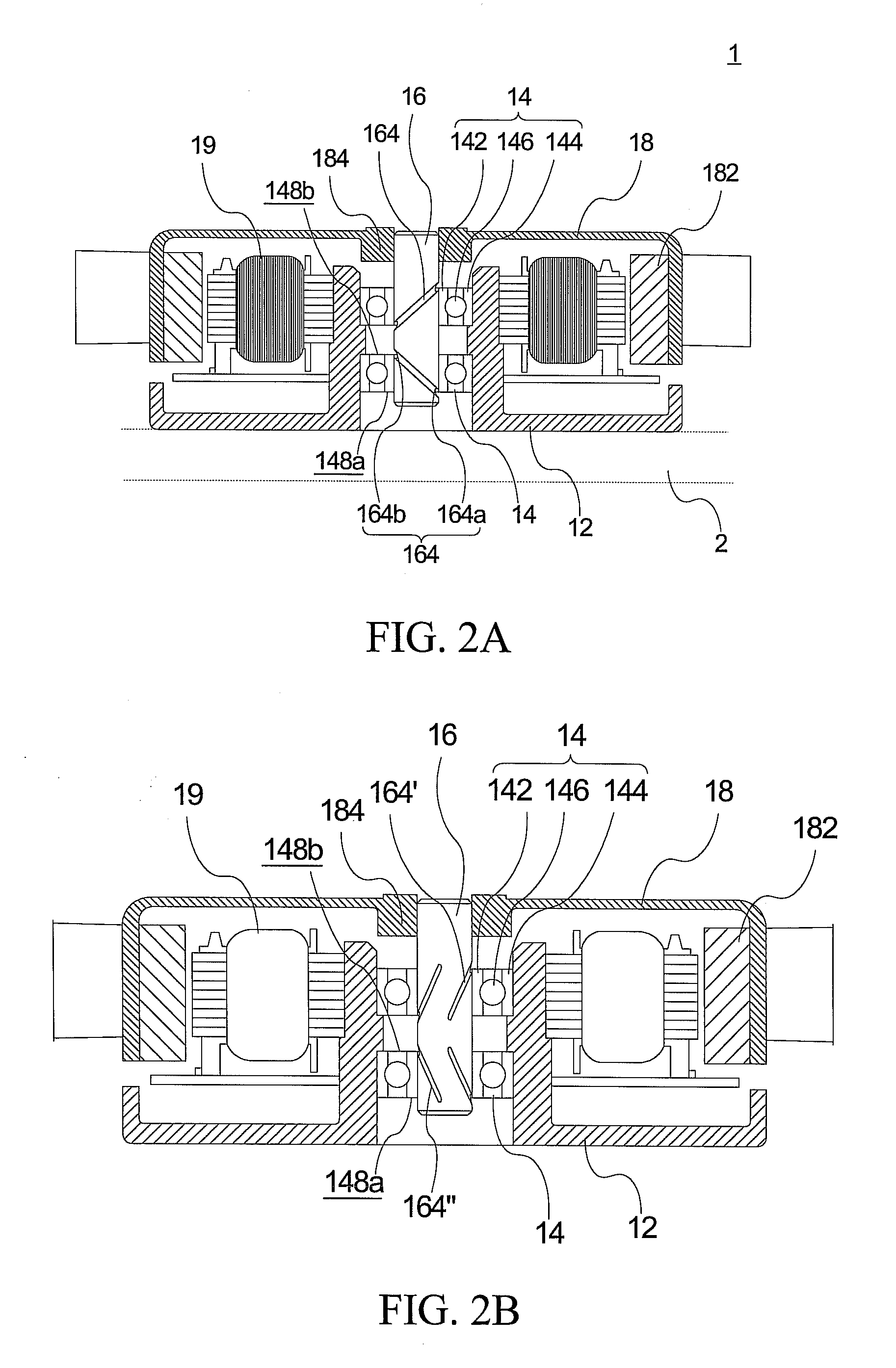
[0024]Please refer to FIG. 2A, FIG. 2A is a cross-sectional view of the fan 1 according to the present invention. The fan 1 includes a base 12, a bearing 14, a shaft 16, an impeller 18, and an electromagnetic element 19. The fan 1 connects to a fixed part 2 (shown as dotted lines) of a system via the base 12.
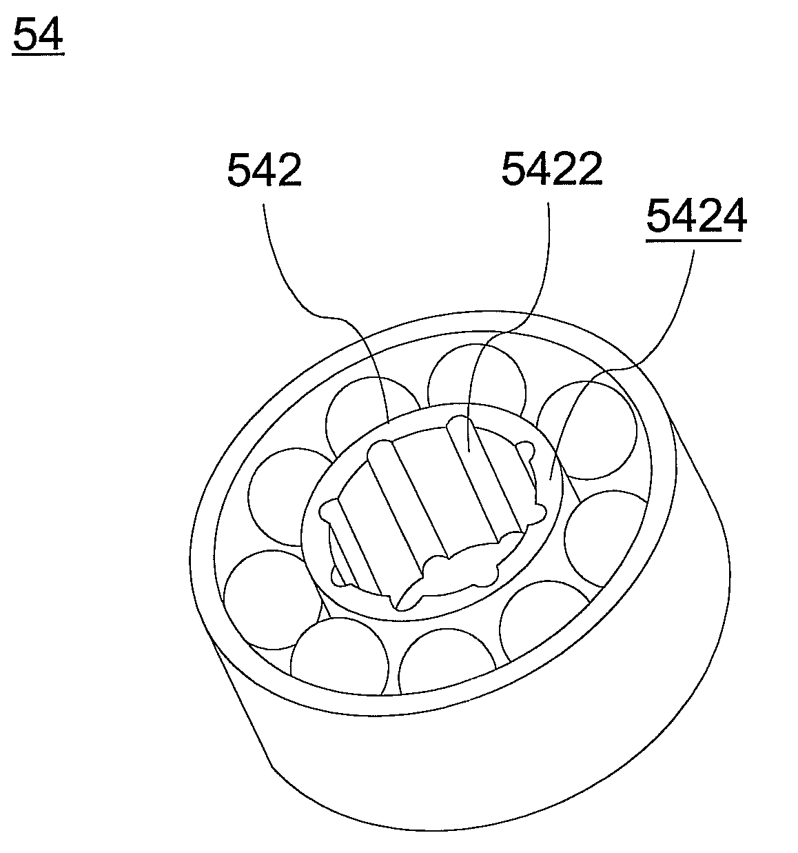
[0025]The base 12 is used for accommodating the bearing 14. The bearing 14 is a ball bearing and includes an inner ring 142, an outer ring 144, and multiple balls 146 disposed between the inner ring 142 and the outer ring 144. The outer ring 144 of the bearing 14 urges against the base 12. A concave structure is formed on the shaft 16, and the concave structure is an annular structure 164 in this embodiment. The shaft 16 passes through the inner ring 142 of the bearing 14 and urges against the inner ring 142. The bearing 14 thereon defines two opposite surfaces 148a and 148b, and the annular concave 164 includes two parts 164a and 164b respectively protruding out of the aforesai...
fourth embodiment
[0027]In the fourth embodiment, the concave structure includes multiple transversal concaves 164a′″ and multiple longitudinal concaves 164b′″ connected to the transversal concaves 164a′″, as shown in FIG. 2D. The aforesaid transverse and longitude are relative to the central axis of the shaft (shown as the dotted line in FIG. 2D). Although the transversal concaves 164a′″ are not directly connected to exterior air, the whole concave structure via the engagements of the longitudinal concaves 164b′″ can allow airflows to pass through the transversal concaves 164a′″ and the longitudinal concaves 164b′″. Additionally, the aforesaid annular concave 164, the oblique concave 164′, and the spiral concave 164″ can be combined alternatively and formed on the surface of the shaft 16.
[0028]Please refer to FIG. 3A, FIG. 3A is a cross-sectional view of the fan 3 according to a fifth embodiment of the present invention. Compared with the aforesaid first embodiment, the concave structure includes mu...
PUM
 Abstract
Description
Claims
Application Information
 - R&D
- Intellectual Property
- Life Sciences
- Materials
- Tech Scout
- Unparalleled Data Quality
- Higher Quality Content
- 60% Fewer Hallucinations
Browse by: Latest US Patents, China's latest patents, Technical Efficacy Thesaurus, Application Domain, Technology Topic, Popular Technical Reports.
© 2025 PatSnap. All rights reserved.Legal|Privacy policy|Modern Slavery Act Transparency Statement|Sitemap|About US| Contact US: help@patsnap.com


