Reverse Dummy Insertion Algorithm

Inactive Publication Date: 2009-07-16
TAIWAN SEMICON MFG CO LTD
View PDF8 Cites 166 Cited by
  • Summary
  • Abstract
  • Description
  • Claims
  • Application Information

AI Technical Summary

Benefits of technology

[0012]The advantageous features of the present invention include reduc

Problems solved by technology

Due to a difference in exposure/etching/polishing rate of a film from one location to another, the amount of reaction produced by the exposure/etching/polishing becomes locally dense or sparse, and hence causes a non-uniformity in etching/polish rates or pattern dimension after exposure.
Big variations in effective pattern densities may result in significant and undesirable effects such as pattern dimension deviation and thickness variation.
The conventio

Method used


Image

  • Reverse Dummy Insertion Algorithm
  • Reverse Dummy Insertion Algorithm
  • Reverse Dummy Insertion Algorithm

Examples


Example

[0018]The making and using of the presently preferred embodiments are discussed in detail below. It should be appreciated, however, that the present invention provides many applicable inventive concepts that can be embodied in a wide variety of specific contexts. The specific embodiments discussed are merely illustrative of specific ways to make and use the invention, and do not limit the scope of the invention.

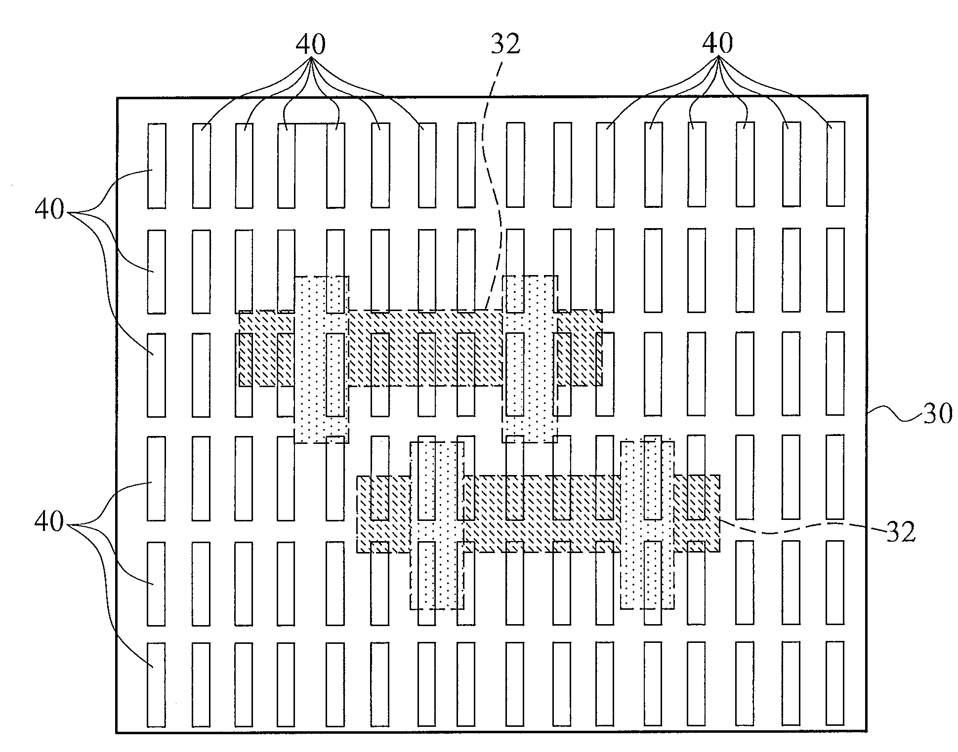
[0019]A method for inserting dummy patterns into layouts of integrated circuit is provided. The intermediate stages of performing the method are provided. The variations of the preferred embodiments are then discussed. Throughout the various views and illustrative embodiments of the present invention, like reference numbers are used to designate like elements.

[0020]Typically, the layouts of integrated circuits are stored in graphic data system (GDS) format, and hence the layout file(s) of integrated circuits are referred to as a GDS file(s) throughout the description. It is r...


PUM


Abstract

A method of inserting dummy patterns includes providing a window area comprising a main pattern. The main pattern includes first patterns of a first type of features, and second patterns of a second type of features. The first and the second types are different types. The method further includes globally inserting first dummy patterns throughout the window area, wherein the first dummy patterns are dummy patterns of the first type of features; enlarging the main pattern to generate an enlarged main pattern, wherein the enlarged main pattern occupies an enlarged region of the window area; removing the portion of the first dummy patterns in the enlarged region from the first dummy patterns to generate first inversed dummy patterns; and combining the first patterns in the main pattern with the first inversed dummy patterns to generate first mask patterns for the first type of features.

Description

TECHNICAL FIELD[0001]This invention relates generally to integrated circuit manufacturing processes, and more particularly to dummy patterns, and even more particularly to algorithms for inserting dummy patterns.BACKGROUND[0002]The pattern effect to the integrated circuit manufacturing processes has been well known as micro-loading effect, which occurs due to differences in pattern densities in a wafer. The micro-loading effect pertains to a phenomenon occurring upon simultaneously exposing, etching and / or polishing a pattern of a higher density and a pattern of a lower density. Due to a difference in exposure / etching / polishing rate of a film from one location to another, the amount of reaction produced by the exposure / etching / polishing becomes locally dense or sparse, and hence causes a non-uniformity in etching / polish rates or pattern dimension after exposure. Big variations in effective pattern densities may result in significant and undesirable effects such as pattern dimension ...

Claims


Application Information

Patent Timeline
IPC IPC(8): G03F1/14G06F17/50
CPCG03F1/144H01L27/0203G03F1/36G03F1/80
Inventor SHYU, JIING-SHINLO, TSENG CHIN
Owner TAIWAN SEMICON MFG CO LTD
Why Eureka
Try Eureka