Spring-loaded dynamic pedicle screw assembly

a dynamic, pedicle screw technology, applied in the field of medical devices and assemblies, can solve the problems of wired implants including an increased risk of damage to neural elements, spinal cord and nerve roots, and screw breakage,

Inactive Publication Date: 2009-07-16
CUSTOM SPINE INC
View PDF10 Cites 74 Cited by
  • Summary
  • Abstract
  • Description
  • Claims
  • Application Information

AI Technical Summary

Benefits of technology

[0010]In view of the foregoing, an embodiment herein provides a new and improved dynamic pedicle screw assembly with intra-operative flexibility, that allows the bone screw to be tensioned in a given zone or range of angulations in the screw head while permitting natural motion. The dynamic pedicle screw assembly includes a fixator component, a clamping mechanism, a screw head, a load sharing mechanism, and a blocker. The fixator component further includes a bulbous end, a neck portion, and a threaded end.

Problems solved by technology

Surgical procedures treating spinal injuries are one of the most complex and challenging surgeries for both the patient and the surgeon.
A common problem with the internal spinal fusion is how to secure the fixation devices without damaging the spinal cord.
However, the wired implants include an increased risk of damage to the neural elements (e.g., spinal cord and nerve roots).
On the other hand, the use of plates with the screws rigidly linked results in the direct transfer of loads at the bone screw interface, which is the weakest link in the fixation spine construction.
This can result in breakage of the screw or failure of the bone screw interface prior to achieving fusion.
In addition, the plate designs are generally bulky and tend to leave little surface for bone grafting and they typically cannot be easily contoured to account for the lateral curvature of the spine.
This smaller and weaker neck portion is significantly further away from the forces being applied through the rod, which consequently allows a bigger moment arm and increases the chance of breakage at the weak neck portion.
Furthermore, most conventional screw assemblies generally do not allow for a bone screw to be tensioned in a given zone or range of angulations in the screw head.
Generally, most artificial discs currently being marketed do not typically offer any resistance at the extreme ranges of motion, and others tend to offer a “dead stop” that may cause implant failure or implant dislodging.
As such, most surgeons would concede that the removal of a failed artificial disc is an extremely undesirable event that is fraught with major complications.
Furthermore, most conventional screw receiving portions do not generally offer enough medial-lateral flexibility because the rod sits too closely on top of the center of rotation of the bone screw producing a smaller arc of rotation.
Moreover, most conventional screw systems do not generally accommodate different rod sizes.
Additionally, most conventional spinal implant designs typically lack features that enhance invasive surgery techniques that are used for spinal surgeries which can decrease the patient's recovery time.
Also, there is generally a lack of limitation of load sharing ability, which may lead to damage of the vertebrae during natural motion.

Method used


Image

  • Spring-loaded dynamic pedicle screw assembly
  • Spring-loaded dynamic pedicle screw assembly
  • Spring-loaded dynamic pedicle screw assembly

Examples


first embodiment

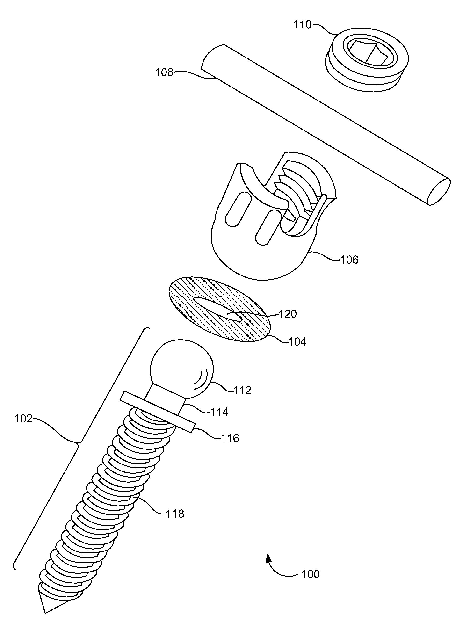
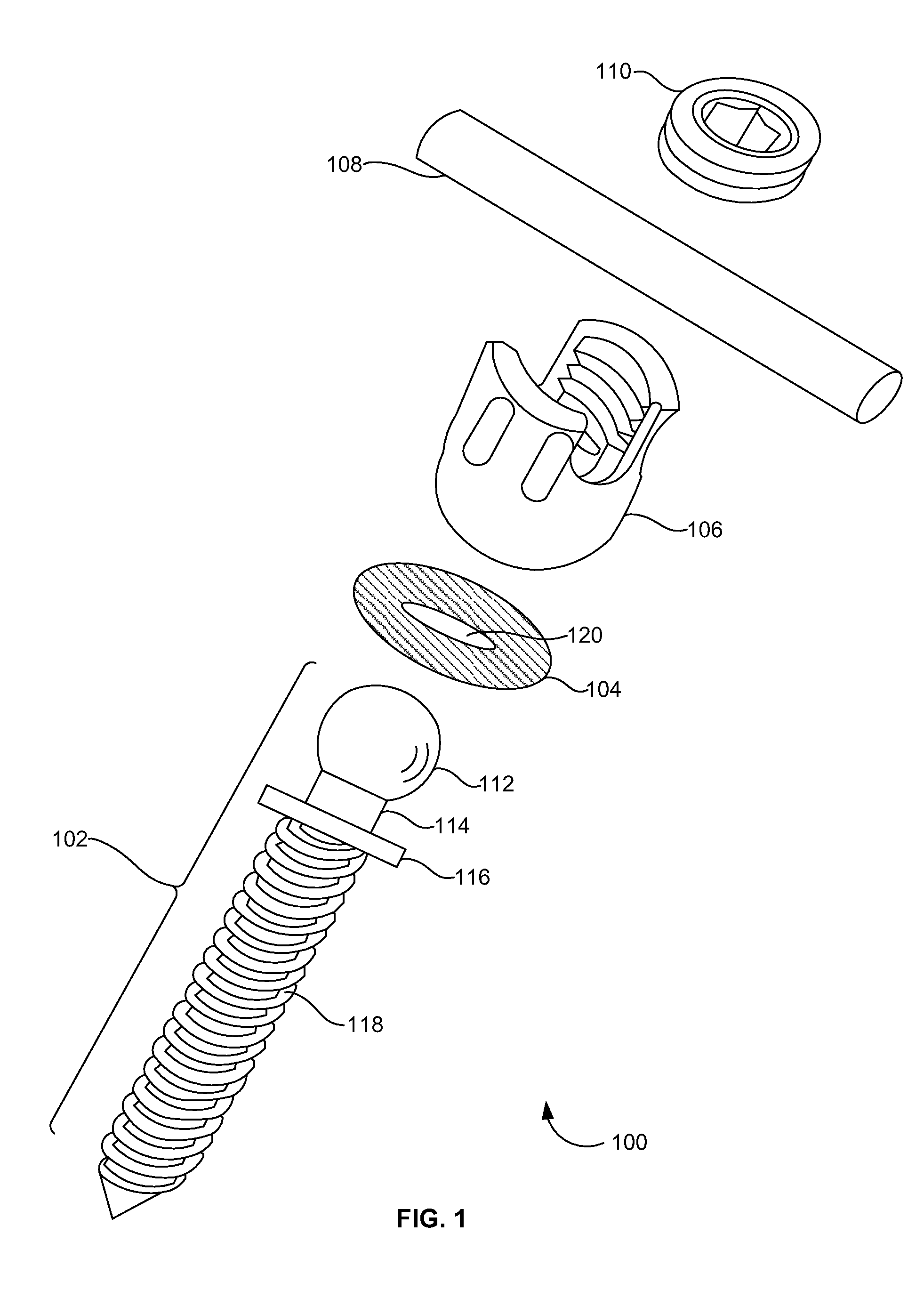
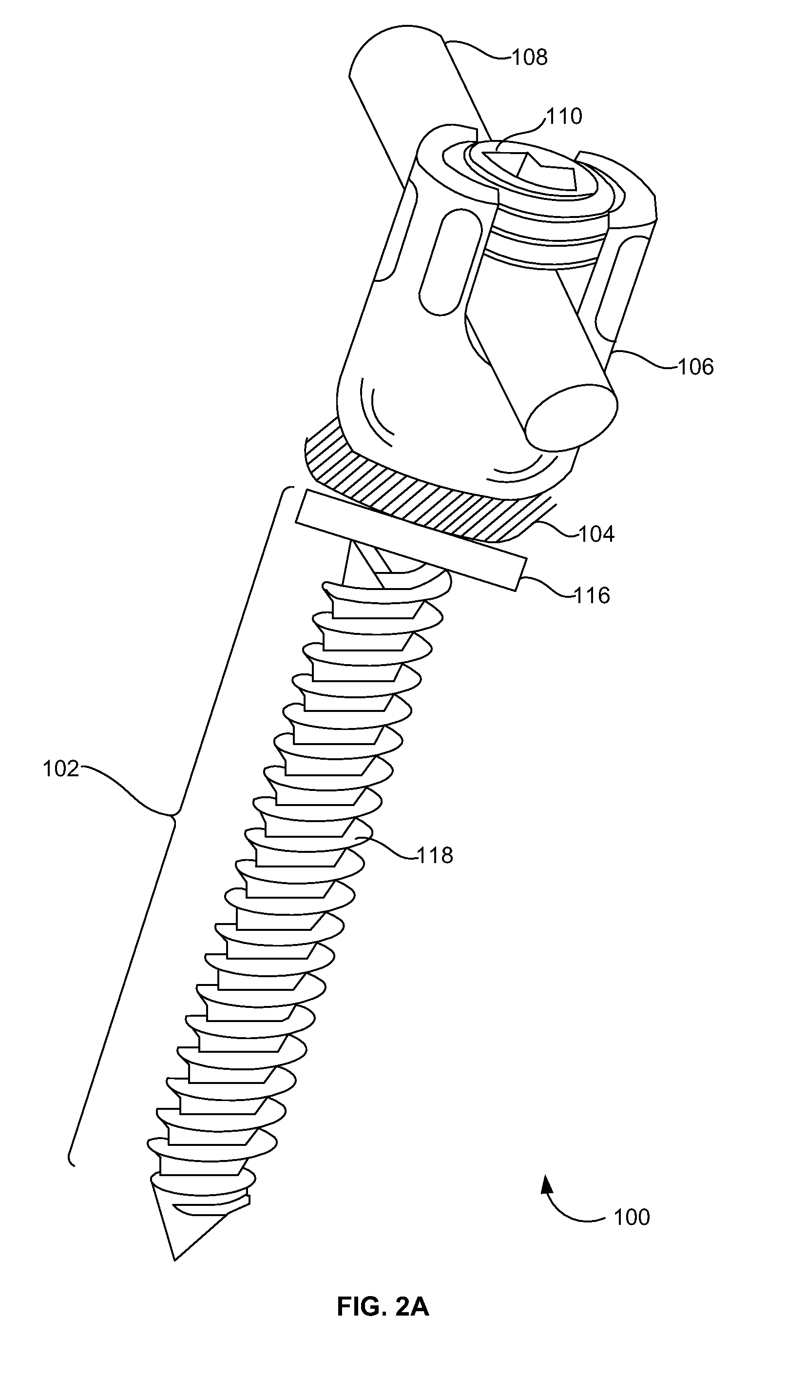
[0042]FIGS. 5A and 5B illustrate an isolated perspective view and a cross-sectional view, respectively, of the screw head 106 and the bone screw 102 interface herein. The load sharing mechanism 104 may be configured as a metallic wave / or hollowed washer 502 that could allow some structural collapse.

second embodiment

[0043]FIGS. 6A and 6B illustrate an isolated perspective view and a cross-sectional view, respectively, of the screw head, and the bone screw 102 interface herein. The load sharing mechanism 104 may be configured as a metallic coiled spring 602. The coiled spring 602 is wrapped into a full diameter and may include an interior rounded washer 604 to further limit the range of motion.

third embodiment

[0044]FIGS. 7A and 7B illustrate an isolated perspective view and a cross-sectional view, respectively, of the screw head and a bone screw 102 interface herein. The load sharing mechanism 104 may be configured as a flexible polymer washer 702 and may comprise silicon or urethane materials, for example.


PUM


Abstract

An assembly that includes a fixator component, a clamping mechanism, a screw head, a load sharing mechanism, and a blocker. The fixator component further includes a bulbous end, a neck portion, and a threaded end. The clamping mechanism is positioned around the neck portion of the fixator component. The load sharing mechanism is positioned in between the screw head and the bone fixator component. The screw head further includes a pair of diametrically opposed arms, a socket and a slot. The socket is positioned between the pair of arms and the slot is positioned above the socket. The socket is dimensioned and configured to house the bulbous end of the fixator component. The load sharing mechanism provides tensile resistance to the screw head and the blocker is adapted to engage the screw head.

Description

BACKGROUND[0001]1. Technical Field[0002]The embodiments herein generally relate to medical devices and assemblies, and more particularly to an orthopedic spring-loaded dynamic pedicle screw assembly used for surgical lumbar, thoracic, and cervical spine treatment.[0003]2. Description of the Related Art[0004]Surgical procedures treating spinal injuries are one of the most complex and challenging surgeries for both the patient and the surgeon. A common problem with the internal spinal fusion is how to secure the fixation devices without damaging the spinal cord. The pedicles are a favored area of attachment since they offer an area that is strong enough to hold the fixation device even when the patient suffers from osteoporosis (e.g., a disease of bone leading to an increased risk of fracture).[0005]More recently, methods of internal fixation have utilized wires that extend through the spinal canal and hold a rod against lamina or that utilize pedicle screws, which extend into the ped...

Claims


Application Information

Patent Timeline
Patent Type & Authority Applications(United States)
IPC IPC(8): A61B17/70A61B17/86
CPCA61B17/8695A61B17/7037
Inventor ABDELGANY, MAHMOUD F.
Owner CUSTOM SPINE INC
Why Eureka
Try Eureka