Solar cell module

a solar cell module and solar cell technology, applied in the field of solar cell modules, can solve the problems of reducing damage accumulated on the connecting portion of the connecting electrode and the wiring member, etc., and achieve the effect of suppressing the decrease in the power collection efficiency of the solar cell modul

Inactive Publication Date: 2009-07-23
PANASONIC INTELLECTUAL PROPERTY MANAGEMENT CO LTD
View PDF5 Cites 43 Cited by
  • Summary
  • Abstract
  • Description
  • Claims
  • Application Information

AI Technical Summary

Benefits of technology

[0012]The present invention has been made in view of the above-described problem. An object of the present invention is to provide a solar cell module capable of suppressing the decrease in power collection efficiency of the solar cell module.

Problems solved by technology

If such stress is kept concentrated on the connecting points, damage is accumulated on connecting portions of the connecting electrodes and the wiring member.
This damage causes poor connection between the connecting electrodes and the wiring member, thus resulting in a problem of a decrease in power collection efficiency of the solar cell module.

Method used


Image

  • Solar cell module
  • Solar cell module
  • Solar cell module

Examples


first embodiment

[0028](First Embodiment)

[0029]

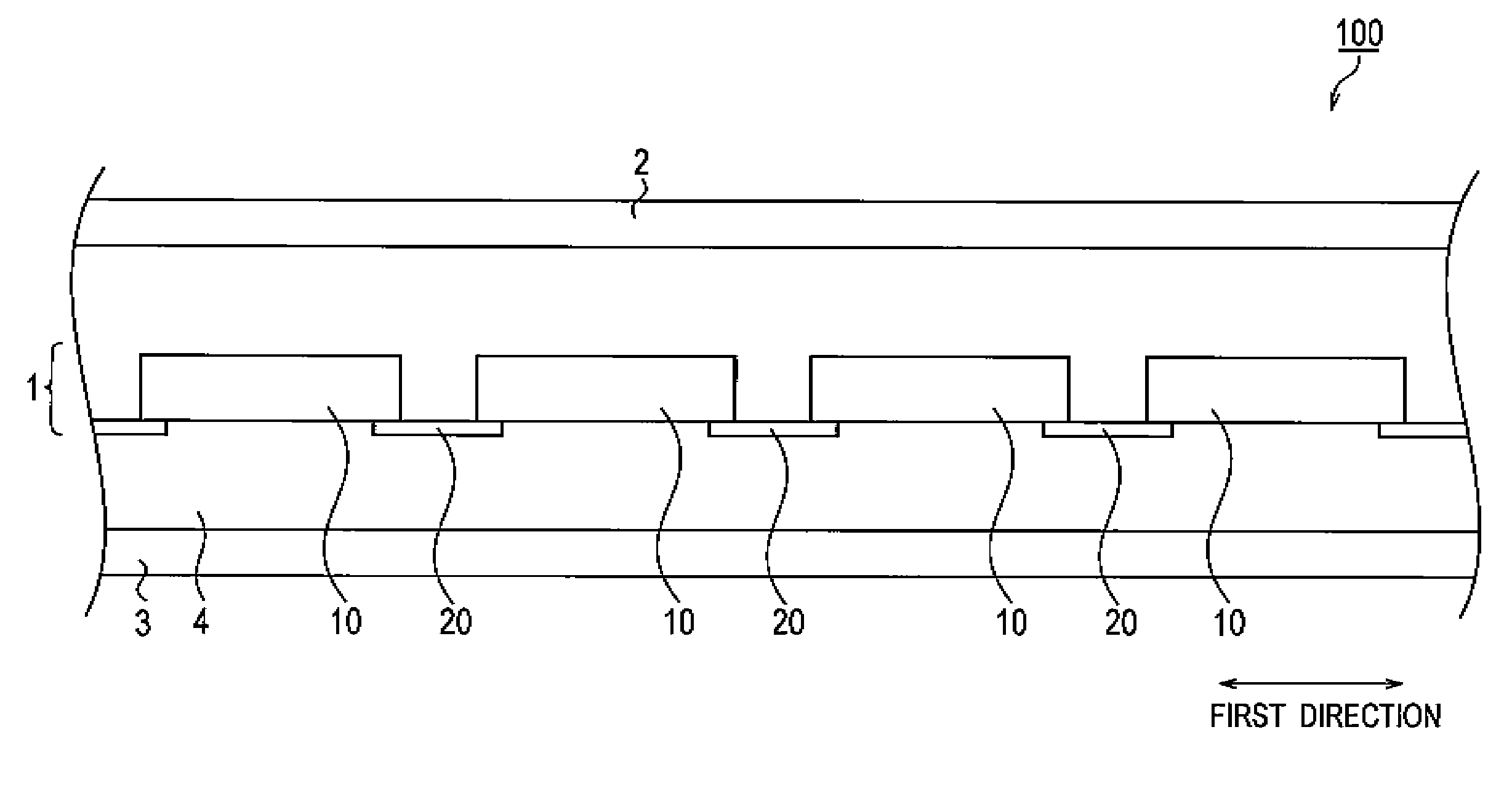
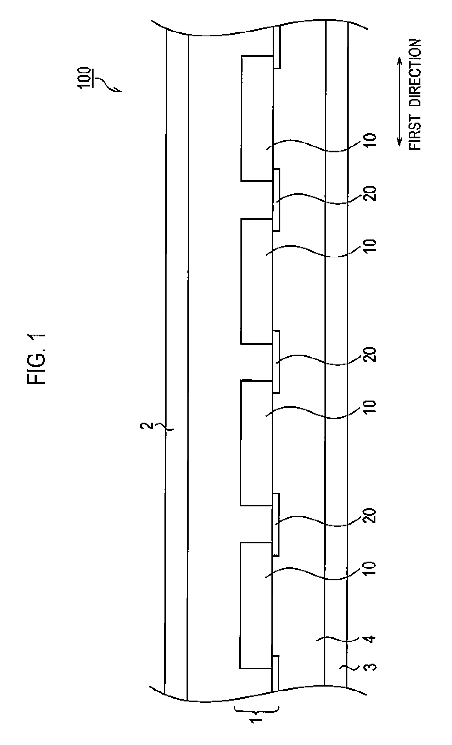
[0030]A schematic configuration of a solar cell module according to a first embodiment of the present invention will be described below by referring to FIG. 1. FIG. 1 is a side view of a solar cell module 100 according to the first embodiment of the present invention.

[0031]As shown in FIG. 1, the solar cell module 100 includes a solar cell string 1, a light-receiving-surface-side protection member 2, a back-surface-side protection member 3, and a sealing member 4.

[0032]The solar cell string 1 includes the plurality of solar cells 10 and the plurality of wiring members 20. The solar cell string 1 is configured in such a way that the plurality of solar cells 10 arranged in a first direction are electrically connected to each other through the plurality of wiring members 20. Each solar cell 10 has a light-receiving surface (upper surface in FIG. 1) receiving sunlight and a back surface (lower surface in FIG. 1) provided on the opposite side of the light-re...

second embodiment

[0069][Second Embodiment]

[0070]A second embodiment of the present invention will be described below. Note that, in the following description, a difference between the first and second embodiments will be mainly described. A solar cell module 100 according to the second embodiment of the present invention has a schematic configuration similar to that of the solar cell module 100 shown in FIG. 1.

[0071]FIG. 6 is a plane view of a solar cell string 1 according to the second embodiment of the present invention seen from the back surface side. Note that, in FIG. 6, n-side finer line-shaped electrodes 15 are omitted for simplifying the drawing, as similar to FIG. 4.

[0072]As shown in FIG. 6, each wiring member 20 has first protruding portions 21a and second protruding portions 21b. The first protruding portions 21a protrude toward a solar cell 10a in the first direction. Meanwhile, the second protruding portions 21b protrude toward a solar cell 10b in the first direction.

[0073]First connect...

third embodiment

[0085][Third Embodiment]

[0086]A third embodiment of the present invention will be described below. Note that, in the following description, a difference between the first and third embodiments will be mainly described. A solar cell module 100 according to the third embodiment of the present invention has a schematic configuration similar to that of the solar cell module 100 shown in FIG. 1.

[0087]FIGS. 8A and 8B are plane views of a solar cell string 1 according to the third embodiment of the present invention seen from the back surface side. Note that, in FIGS. 8A and 8B, n-side finer line-shaped electrodes 15 are omitted for simplifying the drawing, as similar to FIG. 4.

[0088]As shown in FIGS. 8A and B, each wiring member 20 includes slit portions 22 which penetrate the wiring member from one of two main planes of the wiring member substantially parallel to the back surfaces of solar cells 10 to the other main plane of the wiring member provided on the opposite side of the one of t...


PUM


Abstract

To suppress a decrease in power collection efficiency, provided is a solar cell module including; first and second solar cells arranged in a first direction; and a wiring member electrically connecting the first and second solar cells. In the solar cell module, the first and second solar cells each include a light-receiving surface receiving light, a back surface provided on the opposite side of the light-receiving surface, and p-side and n-side electrodes formed on the back surface; the wiring member is connected to the n-side electrode of the first solar cell at a first connecting point, and connected to the p-side electrode of the second solar cell at a second connecting point; and, in a planar view of the back surface, the first and second connecting points are located on a line intersecting with the first direction.

Description

CROSS REFERENCE TO RELATED APPLICATIONS[0001]This application is based upon and claims the benefit of priority from prior Japanese Patent Application No. 2008-010972, filed on January 21; the entire contents of which are incorporated herein by reference.BACKGROUND OF THE INVENTION[0002]1. Field of the Invention[0003]The present invention relates to a solar cell module including a plurality of solar cells arranged in a predetermined direction, and wiring members connecting the plurality of solar cells to each other.[0004]2. Description of the Related Art[0005]Solar cells directly convert clean and unlimitedly-supplied sunlight into electricity, and thus are expected as one of new energy sources.[0006]In general, energy output per solar cell is approximately several watts. Accordingly, when solar cells are used as a power source for a house, a building or the like, a solar cell module is used in which the plurality of solar cells are electrically connected to each other to enhance ene...

Claims


Application Information

Patent Timeline
Patent Type & Authority Applications(United States)
IPC IPC(8): H01L31/042
CPCH01L31/02245Y02E10/50H01L31/0516
Inventor HISHIDA, YUJI
Owner PANASONIC INTELLECTUAL PROPERTY MANAGEMENT CO LTD
Why Eureka
Try Eureka