
Optical detection system for micromechanical cantilevers, especially in scanning probe microscopes

a detection system and micromechanical technology, applied in the direction of beam/ray focussing/reflecting arrangement, instruments, electric discharge lamps, etc., can solve the problems of hardly adaptable cantilever-based spm solution to any of the typical cantilever-based spm, and achieve the effect of facilitating venting of the cavity

Inactive Publication Date: 2009-07-23
NANOSURF
View PDF10 Cites 4 Cited by
  • Summary
  • Abstract
  • Description
  • Claims
  • Application Information

AI Technical Summary

Benefits of technology

[0031]When changing the fluid from a gaseous to a liquid medium, care should be taken in order to avoid remaining gas bubbles in the cavity of the interface. This can easily be achieved by controlling the wetting properties of the surface and / or by introducing a geometrical set-up which facilitates venting of the cavity.

Problems solved by technology

However, the description of the optical detector system therein does not address any implications based on measuring in a liquid.
Though the disclosed system addresses some of the issues occurring when fluids having different refractive indices are changed within an optical beam path, the disclosed solution of a reflector within a probe chamber seems hardly adaptable to any of the typical cantilever-based SPMs.
However, as shown in U.S. Pat. No. 5,517,360 by Suzuki and U.S. Pat. No. 5,805,346 by Tomimatso, both addressing immersion microscope objectives, the disclosed objectives are extremely complex designs, consisting of ten or more lenses with detailed specifications.
It seems that the issue of re-adjustment and / or re-calibration was not recognized or it was considered immaterial or not sufficiently important in a scientific environment.
(2) It becomes worse when the incident beam enters the probe chamber under an angle or the reflected beam leaves the probe chamber under an angle, i.e. passes the chamber walls not perpendicularly.
Though this may be acceptable in a test or laboratory environment, it is certainly not acceptable in an industrial or manufacturing environment.
Also, it makes measurements whereby the fluid is to be changed under way, i.e. during the measurement, practically impossible.

Method used


Image

  • Optical detection system for micromechanical cantilevers, especially in scanning probe microscopes
  • Optical detection system for micromechanical cantilevers, especially in scanning probe microscopes
  • Optical detection system for micromechanical cantilevers, especially in scanning probe microscopes

Examples


first embodiment

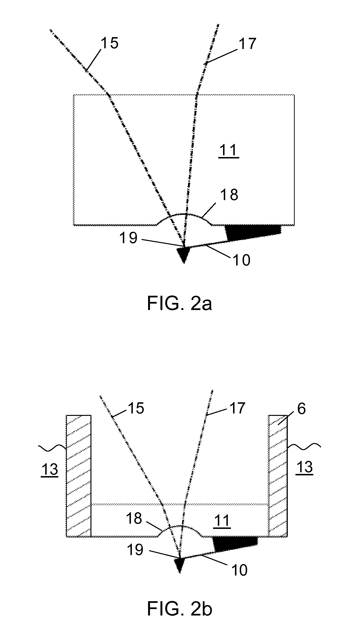
[0035]FIG. 3 is a detail view of the optical element;

second embodiment

[0036]FIG. 4 is a detail view of the optical element; and

[0037]FIG. 5 is a further embodiment with separate optical elements.

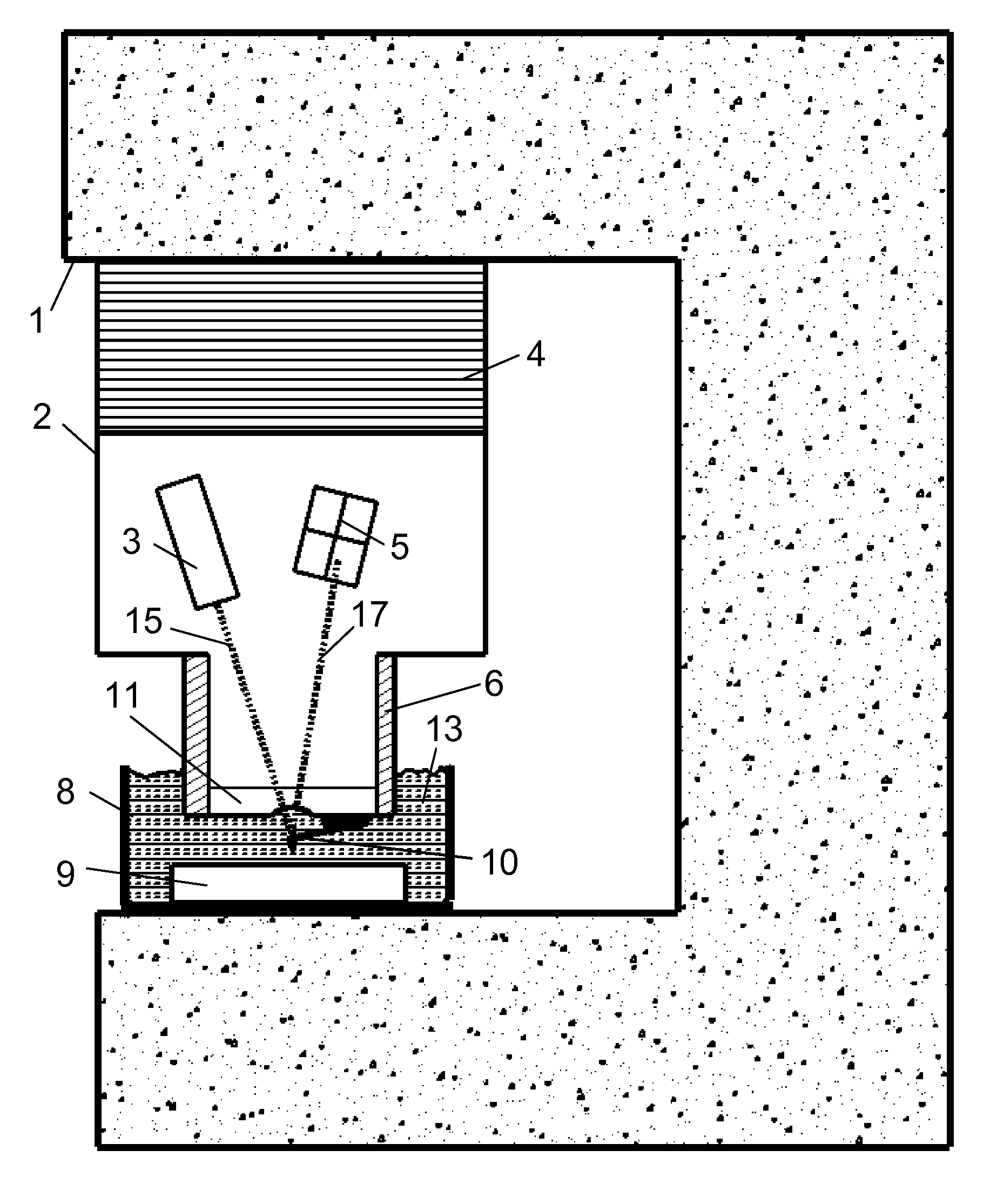
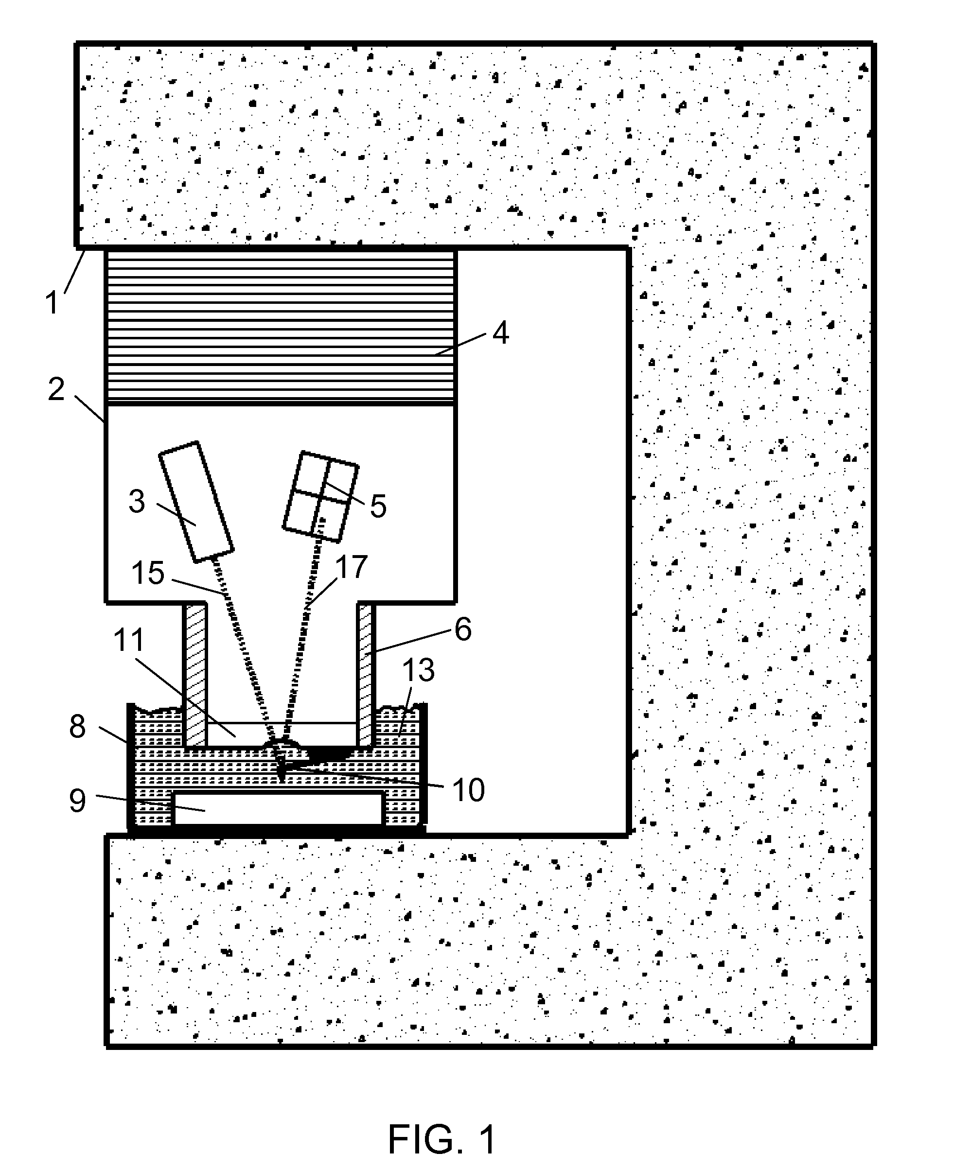
[0038]FIG. 1 shows a typical AFM in which the present invention may be used whenever samples in fluids are to be investigated or measured.

[0039]The stationary body 1 of the AFM is shown schematically only; only the parts important for the present invention are depicted in some detail. Housing 2 comprises the optical arrangement consisting of a laser 3 and a receiver or sensor diode 5, the latter being e.g. a four-quadrant diode. An x-y-z positioning device 4 can move housing 2 in three dimensions as known in the AFM art. A tube-like extension 6 of housing 2 reaches into fluid 13 which fills probe chamber 8. The bottom end of extension 6 is closed by a transparent optical element 11 which provides the separating element between the fluid 13 and the inside of housing 2. The latter is usually air-filled.

[0040]Sample 9 which is to be investigated is located at the...


PUM


Abstract

The optical detection system typically used in micromechanical cantilever-based instruments, e.g. scanning probe microscopes, chemical or biological sensing probes like “artificial noses”, or molecular force probe instruments, can hardly cope when measuring samples immersed in a fluid, i.e. a gas, gel, or liquid having another refractive index than the environment. Optical readout or detection becomes problematic as soon as the refractive index of the fluid changes, because signals can shift significantly. The invention provides an improved optical means at the interface between the fluid and the environment, avoiding signal shifts, and thus avoiding time-consuming and difficult re-calibration or re-adjustment of the microscope or other cantilever-based instrument.

Description

TECHNICAL FIELD OF THE INVENTION [0001]The present invention concerns an improvement for the optical detection system used typically within micromechanical cantilever-based instruments. In such instruments, one or more micromechanical cantilevers whose deflection or movement, e.g. oscillation, is often detected or read out optically. Such cantilevers are used for investigating materials in various applications, particularly interesting applications being scanning probe microscopes (SPMs) like atomic force microscopes (AFMs), chemical or biological sensing probes like “artificial noses”, or molecular force probe instruments, etc. Lately, science has become very interested in investigating probes or samples in a fluid, i.e liquid, gel or gas, or even samples whose environment must be changed during or between measurements. Optical readout or detection becomes problematic when the measurement environment of the sample changes from a first fluid to a second fluid with a different refrac...

Claims


Application Information

Patent Timeline
IPC IPC(8): G01N23/00
CPCB82Y35/00G01Q30/14G01Q20/02
Inventor HOWALD, LUKAS E.
Owner NANOSURF
Learn More