
Liquid Crystal Display

a liquid crystal display and display technology, applied in static indicating devices, instruments, non-linear optics, etc., can solve the problems of deteriorating image difficult to accurately represent colors, and severe reduction of image quality, so as to improve the display quality of liquid crystal displays and improve color reproduction ranges.

Active Publication Date: 2009-07-23
LG DISPLAY CO LTD
View PDF5 Cites 7 Cited by
  • Summary
  • Abstract
  • Description
  • Claims
  • Application Information

AI Technical Summary

Benefits of technology

[0019]An object of the present invention is to provide a liquid crystal display capable of improving a color reproduction range.
[0028]According to the present invention, the pixel electrodes are formed to have the same opening ratio in the individual pixel regions forming a unit pixel by changing the shape and size of the pixel electrodes in a region having a sensor and a region without a sensor, thereby improving a color reproduction range and improving the display quality of the liquid crystal display.

Problems solved by technology

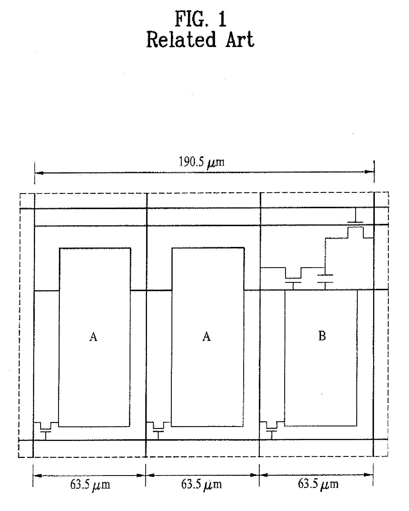
Accordingly, in the individual pixels having the same dot pitch, since color mixture is not properly made due to a difference in an opening ratio of the unit pixel without a sensor and the unit pixel having a sensor, it is difficult to accurately represent colors.
Thus, there is a problem of deteriorating image quality in the liquid crystal display.
Further, in a case where one or more individual pixels include a sensor in the liquid crystal display having a sensor, the reduction of image quality becomes severer.

Method used


Image

  • Liquid Crystal Display
  • Liquid Crystal Display
  • Liquid Crystal Display

Examples


first embodiment

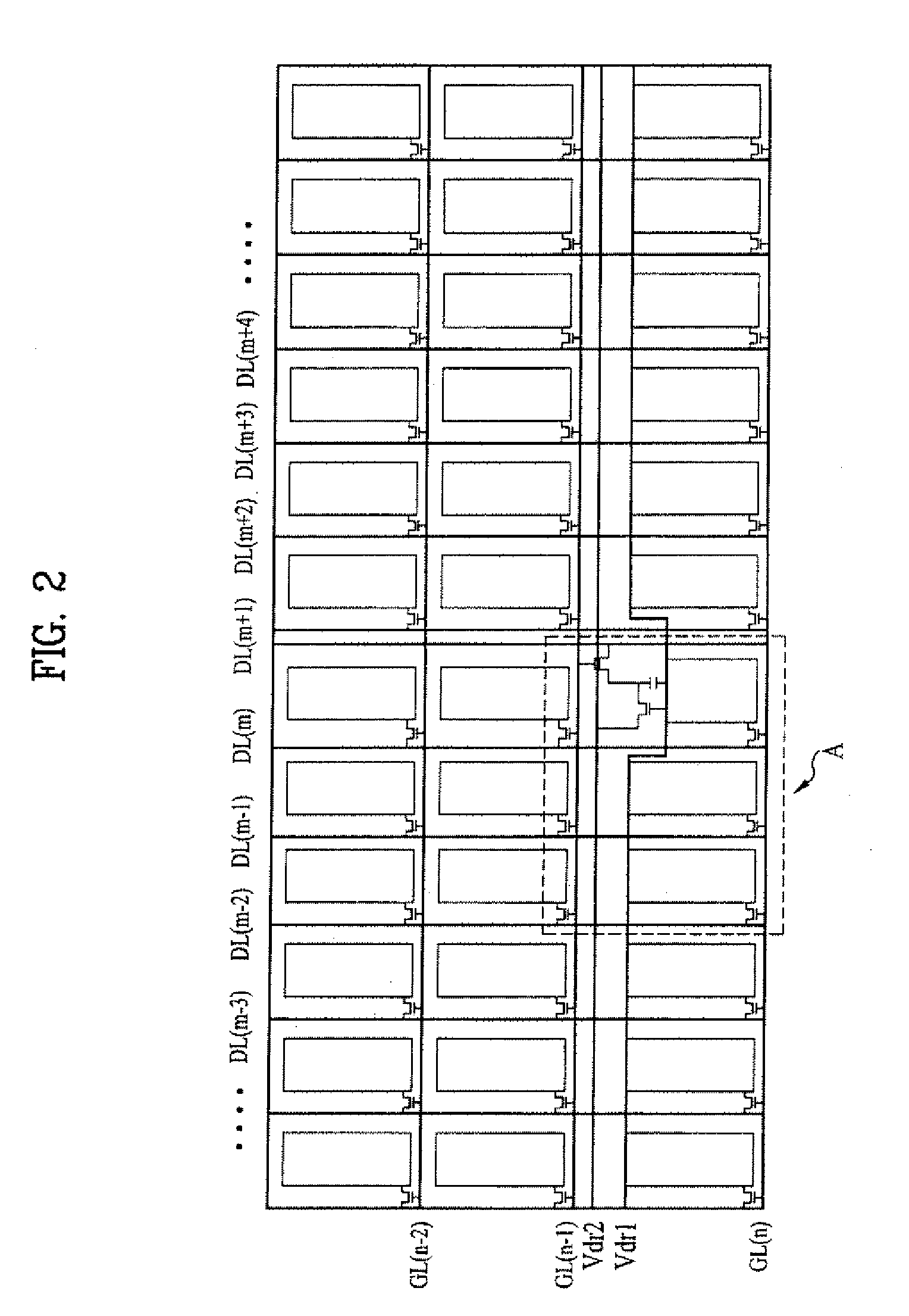
[0041]FIG. 2 illustrates a liquid crystal panel of a liquid crystal display according to the embodiments of the present invention. FIG. 3 illustrates a unit pixel region of the liquid crystal display according to the present invention.

[0042]Referring to FIGS. 2 and 3, the liquid crystal display includes a liquid crystal panel 102 having a plurality of gate lines GL(1) to GL(n) and a plurality of data lines DL(1) to DL(m) which cross each other to define a plurality of unit pixel regions, a first pixel region 104 having a first dot pitch DP1 among individual pixel regions in each unit pixel region A of the liquid crystal panel, and a second pixel region 106 having a second dot pitch DP2 among the individual pixel regions in each unit pixel region A. The first and second dot pitches DP1 and DP2 of the first and second pixel regions 104 and 106 are different from each other.

[0043]The liquid crystal panel 102 includes a plurality of individual pixel regions in which the gate lines GL(1)...

second embodiment

[0058]FIG. 8 illustrates a liquid crystal display according to the present invention.

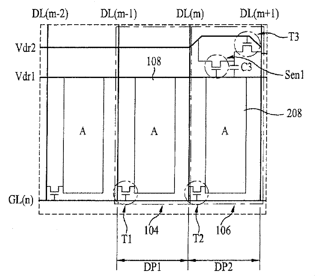
[0059]Referring to FIG. 8, in the liquid crystal display according to the second embodiment of the present invention, in a case of a 7″ WVGA liquid crystal panel having the same conditions as in the first embodiment, a unit pixel region has a total dot pitch of 195.2 μm. In this case, in each unit pixel region including the red (R), green (G) and blue (B) individual pixel regions, the pixel electrodes of the red (R), green (C) and blue (B) individual pixel regions overlap with the first driving voltage supply line Vdr1, and the pixel electrodes 108 and 208 are formed to have first and second areas of the same area. In this case, the first and second pixel regions 104 and 106 are formed to have different dot pitches DP1 and DP2.

[0060]In other words, in order to arrange the Sen1 for sensing light from the outside, the third capacitor C3 for storing a signal sensed by the sensor Sen1, and the third thi...


PUM

PropertyMeasurementUnit
areaaaaaaaaaaa
voltageaaaaaaaaaa
driving voltageaaaaaaaaaa

Abstract

A liquid crystal display capable of improving a color reproduction range is disclosed. The liquid crystal display includes a liquid crystal panel having a plurality of gate lines and a plurality of data lines which cross each other to define a plurality of unit pixel regions; a first pixel region having a first dot pitch among individual pixel regions in at least one of the unit pixel regions; and a second pixel region having a second dot pitch among the individual pixel regions in the unit pixel regions, wherein the first and second dot pitches of the first and second pixel regions are different from each other. By this configuration, the pixel electrodes are formed to have the same opening ratio in the individual pixel regions forming a unit pixel by changing the shape and size of the pixel electrodes in a region having a sensor and a region without a sensor, thereby improving a color reproduction range and improving the display quality of the liquid crystal display.

Description

CROSS-REFERENCE TO RELATED APPLICATION[0001]This application claims the benefit of Korean Patent Application No. 10-2007-106046, filed on Oct. 22, 2007, which is hereby incorporated by reference in its entirety as if fully set forth herein.BACKGROUND OF THE INVENTION[0002]1. Field of the Invention[0003]The present invention relates to a liquid crystal display, and more particularly to a liquid crystal display capable of improving a color reproduction range.[0004]2. Discussion of the Related Art[0005]Generally, flat plate displays include a liquid crystal display, a field emission display, a plasma display panel, a light emitting device and the like.[0006]The liquid crystal display displays an image by adjusting a light transmittance of liquid crystal using an electric field. For this, an image display device includes a display panel having liquid crystal cells, a back light unit which illuminates light on the display panel and a driving circuit for driving the liquid crystal cells.[...

Claims


Application Information

Patent Timeline
Patent Type & Authority Applications(United States)
IPC IPC(8): G02F1/136G02F1/1343
CPCG02F2001/13312G02F1/134309G02F1/13312G02F1/133
Inventor KIM, YOUNG SIKCHOO, KYO SEOPKIM, TAE HWAN
Owner LG DISPLAY CO LTD
Learn More