
Laser light source device, image display and illuminator

Active Publication Date: 2010-09-30
PANASONIC CORP
View PDF4 Cites 8 Cited by
  • Summary
  • Abstract
  • Description
  • Claims
  • Application Information

AI Technical Summary

Benefits of technology

[0041]An object of the invention is to provide a laser light source device having high reliability against fiber deterioration caused by residual pumping light and capable of increasing an output of oscillation light.
[0043]In the laser light source device described above, because the residual pumping light in the fiber laser portion is used as the pump light source in the fiber amplifier portion, it is possible to prevent deterioration of the fiber that raises a problem when generating light at a high output. Further, the output can be enhanced further without having to additionally provide a pump light source for the fiber amplifier portion. It is thus possible to obtain a sufficient output as the light source applied to an image display using a laser. Accordingly, an image display using this light source is capable of widening the color reproduction range in comparison with a conventional solid-state laser.
[0044]Further, laser light in a 915-nm band in which the absorption spectrum of the rare-earth fiber is broad can be used as pumping light in the fiber laser portion. Accordingly, the need to accurately control the temperature of the pump laser is eliminated and a Peltier element can be omitted. Power consumption can be therefore reduced.

Problems solved by technology

As is described in Patent Document 1, because pumping light and oscillation light propagate on the same fiber in the fiber laser or the fiber amplifier, part of oscillated light becomes accidental return light and may possibly damage the pump light source.
However, in a case where the wavelength conversion light source employing the fiber laser as the fundamental light source is used, the operation of the laser resonator (oscillation) becomes unstable because there is absorption of light at 1075 nm or shorter, which is the fundamental harmonic within the wavelength range specified above, in the rare-earth-doped fiber, which is a laser medium.
This makes it impossible to extend the fiber length, which is an interaction length.
However, depending on the wavelength of the pumping light, the pumping light that was not absorbed in the rare-earth-doped fiber, which is a laser medium, causes a problem that the fiber deteriorates.
However, at the wavelength, such as 1060 nm and 1050 nm, at which green can be produced through wavelength conversion, it is known that extending the length of the rare-earth-doped double clad polarization maintaining fiber makes a considerable loss resulting from fiber absorption, which raises problems that the oscillation becomes unstable and the light fails to oscillate at a desired wavelength.
As has been described, it has been difficult to achieve the temperature stability of the fiber laser device and to obtain linearly polarized light at 1070 nm or shorter having power of 10 W or higher using the fiber laser at the same time.
The material costs are increased because of these two factors.
Moreover, because points at which the fiber is fusion spliced are increased, there is a drawback that the device becomes less reliable.
In addition, depending on the oscillation wavelength, signal light that can be generated in the fiber laser portion fails to achieve satisfactory intensity.
This raises a need to adopt a multi-stage configuration by connecting more than one fiber amplifier portion in series, and thereby poses a problem that the material costs are increased.
Hence, the pumping light has to be decreased as the oscillation wavelength becomes shorter, which makes it difficult to achieve a high output.
As has been described, the fiber laser and the fiber amplifier of the conventional configuration in FIG. 11 is available for laboratory use but is not readily applied to industrial and commercial use.

Method used


Image

  • Laser light source device, image display and illuminator
  • Laser light source device, image display and illuminator
  • Laser light source device, image display and illuminator

Examples


first embodiment

[0060]A first embodiment of the invention is a case where a fiber laser and a fiber amplifier both using a polarization maintaining fiber are combined.

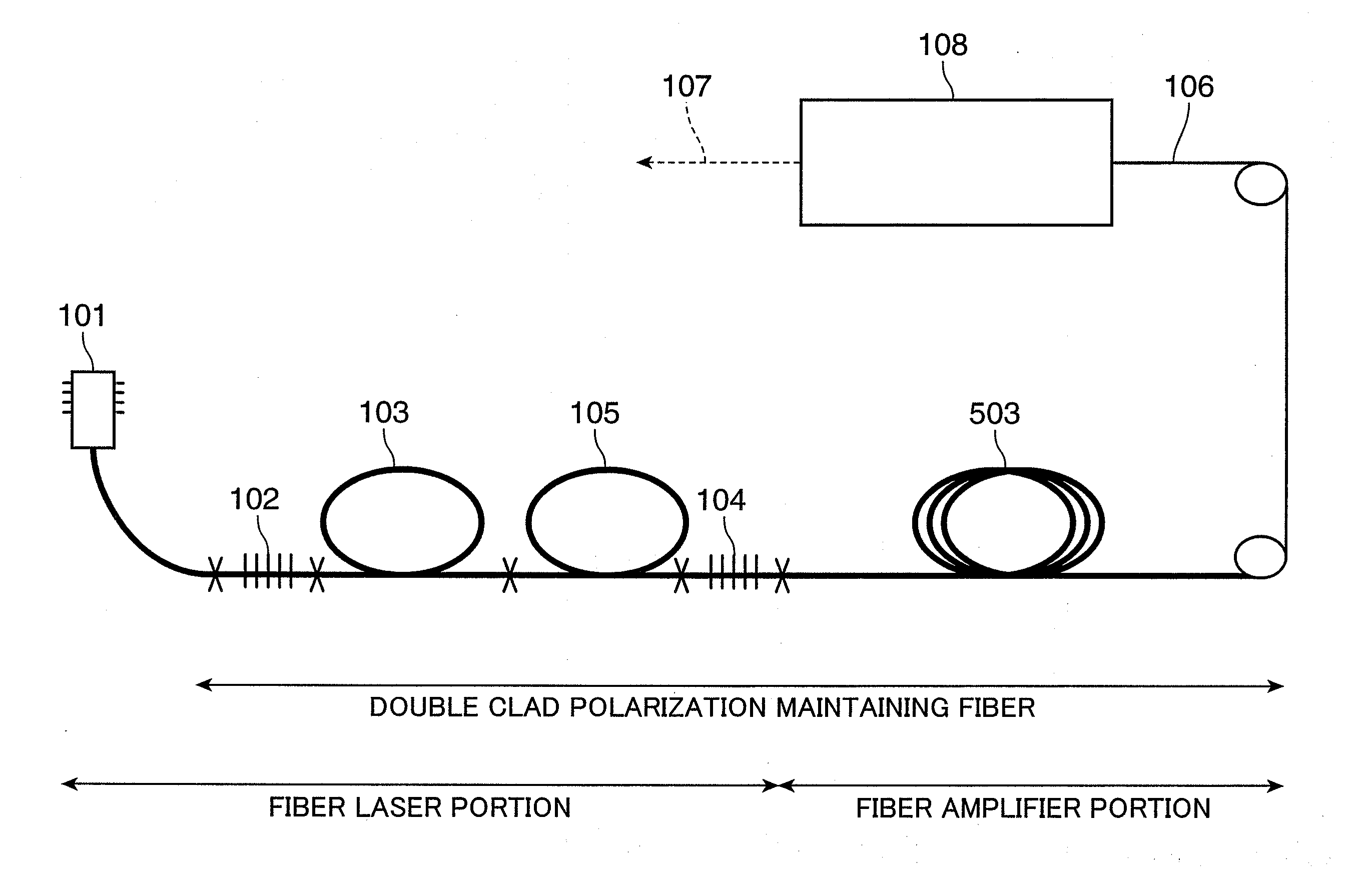
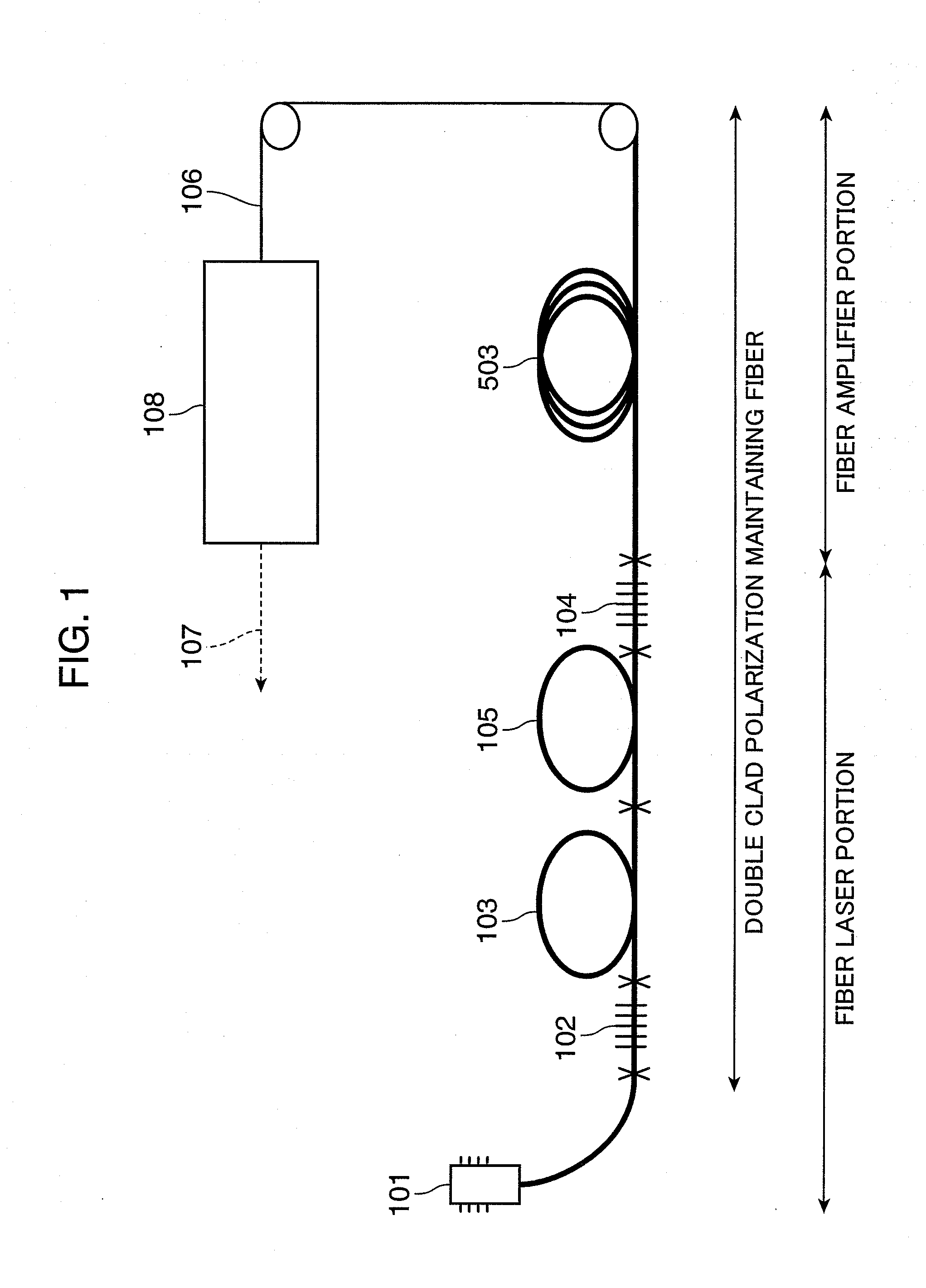
[0061]FIG. 1 shows the configuration of a laser light source device according to the first embodiment of the invention. Referring to FIG. 1, the laser light source device of this embodiment includes a fiber laser portion and a fiber amplifier portion. The fiber laser portion includes a pump LD 101, a fiber grating 102, an Yb-doped double clad polarization maintaining fiber 103, a fiber grating 104, and a polarizer 105. The fiber amplifier portion includes an Yb-doped double clad polarization maintaining fiber 503. Both the fiber laser portion and the fiber amplifier portion are made of a double clad polarization maintaining fiber. Signal light generated in the fiber laser portion is amplified in the fiber amplifier portion. The laser light source device of this embodiment is connected to a second-harmonic generation (SHG) module 108 v...

second embodiment

[0096]As a second embodiment of the invention, the configuration to generate light at 515 nm through the second harmonic generation from the fundamental harmonic at 1030 nm will be described. It is possible to replace a high output Ar ion laser with a laser light source device of this embodiment.

[0097]A difference of the laser light source device of this embodiment from the laser light source device of the first embodiment above is the length of the Yb-doped fiber 103 used in the fiber laser portion in FIG. 1. Hereinafter, the difference will be described. The laser light source device of this embodiment can be achieved by the same configuration as that of the laser light source device of the first embodiment above except for the length of the Yb-doped fiber 103.

[0098]When generating light at 1030 nm, the wavelength cannot be selected in the fiber grating 104 when the fiber length exceeds 3 m, and the oscillation wavelength becomes unstable. This is because a loss in the Yb-doped fi...

third embodiment

[0107]The laser light source devices described in the first embodiment and the second embodiment above are used as a display light source in a laser display (image display), a backlight light source in a liquid crystal display, or a light source in an ornament illuminator.

[0108]As an example of the use of the laser light source devices descried in the first embodiment and the second embodiment above, an example of the configuration of a laser display (image display) to which the laser light source devices are applied will be described using FIG. 5.

[0109]Laser light sources 1201a through 1201c of three colors, red (R), green (G), and blue (B), are used in the laser light source device. A GaAs semiconductor laser having the wavelength of 638 nm is used as the red laser light source 1201a and a GaN semiconductor laser having the wavelength of 465 nm is used as the blue laser light source 1201c. Also, a wavelength conversion green light source device provided with a wavelength conversio...


PUM


Abstract

There is a problem that in the connection portion between a rare-earth-doped double clad fiber and a single mode fiber, pumping light leaks in a portion having the coating, and the fiber generates heat partially with this energy and deteriorates. Also, there is another problem that the output is limited as the oscillation wavelength becomes shorter. Accordingly, in a laser light source device formed by combining a fiber laser and a fiber amplifier, by using the residual pumping light in the fiber laser as the pumping light in the fiber amplifier, it is possible to enhance the reliability by preventing the fiber deterioration caused by the residual pumping light. Further, by amplifying the output in the fiber amplifier in the latter stage without any limitation on the pumping light output, it is possible to increase an output of the oscillation light.

Description

TECHNICAL FIELD[0001]The present invention relates to a laser light source device formed by combining a fiber laser and a fiber amplifier and to an image display and an illuminator utilizing the laser light source device.BACKGROUND ART[0002]A fiber laser light source characterized by its high oscillation efficiency, excellent beam quality, capability of employing air cooling, and simple structure has been attracting attention recently as a near-infrared laser light source that replaces a solid-state laser light source that has been conventionally used.[0003]FIG. 7 shows a schematic view showing the configuration of a typical fiber laser light source. Laser light emitted from a pump LD 101 goes incident on a rare-earth-doped clad pump fiber 103, which is a laser medium, and the laser light oscillates as it is resonated in a laser resonator formed of fiber gratings 102 and 104, which are reflection mirrors.[0004]A polarizer 105 is interposed in order to align polarization directions o...

Claims


Application Information

Patent Timeline
IPC IPC(8): H01S3/30H01S3/00F21V8/00
CPCG02B6/001H01S3/0675H01S3/06754H01S3/094003G03B33/12H01S3/2383G03B21/2033G03B21/2093H01S3/094007G03B21/20
Inventor FURUYA, HIROYUKIYAMAMOTO, KAZUHISAMIZUUCHI, KIMINORI
Owner PANASONIC CORP
Learn More