Color image display device and color conversion device
a color conversion device and display device technology, applied in the direction of television systems, instruments, color signal processing circuits, etc., can solve problems such as unnatural reproduction, and achieve the effect of extending the color reproduction range and enhancing saturation
- Summary
- Abstract
- Description
- Claims
- Application Information
AI Technical Summary
Benefits of technology
Problems solved by technology
Method used
Image
Examples
first embodiment
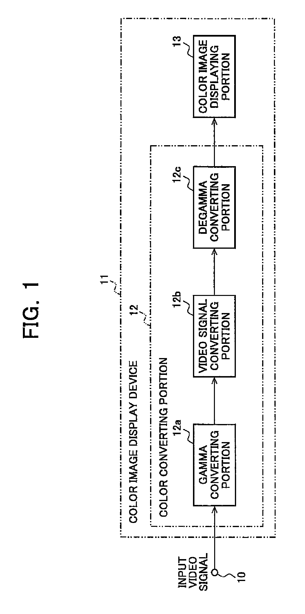
[0043]FIG. 1 is a block diagram of an exemplary configuration of a display device according to a first embodiment of the present invention; in FIG. 1, a reference numeral 10 denotes an input video signal; 11 denotes a color image display device; 12 denotes a color converting portion; and 13 denotes a color image displaying portion. The input video signal 10 is color-converted by the color converting portion 12 and displayed by the color image displaying portion 13.
[0044]The color converting portion 12 corresponds to a color conversion device of the present invention, and includes a gamma converting portion 12a that performs gamma conversion for the input video signal 10, a video signal converting portion 12b that performs a converting processing of a gamma-converted RGB signal, and a degamma conversion portion 12c that performs degamma conversion using the inverse function of gamma characteristics of the color image displaying portion 13. These portions will be described in detail l...
second embodiment
[0113]A second embodiment of the present invention will then be described.
[0114]This embodiment is an example of a method for defining the third color space without LUT or weighting correction mentioned in the first embodiment in such a case that the color reproduction range of the display device is not so much larger than that in the first color space and the transfer function of the display device can be represented by a matrix.
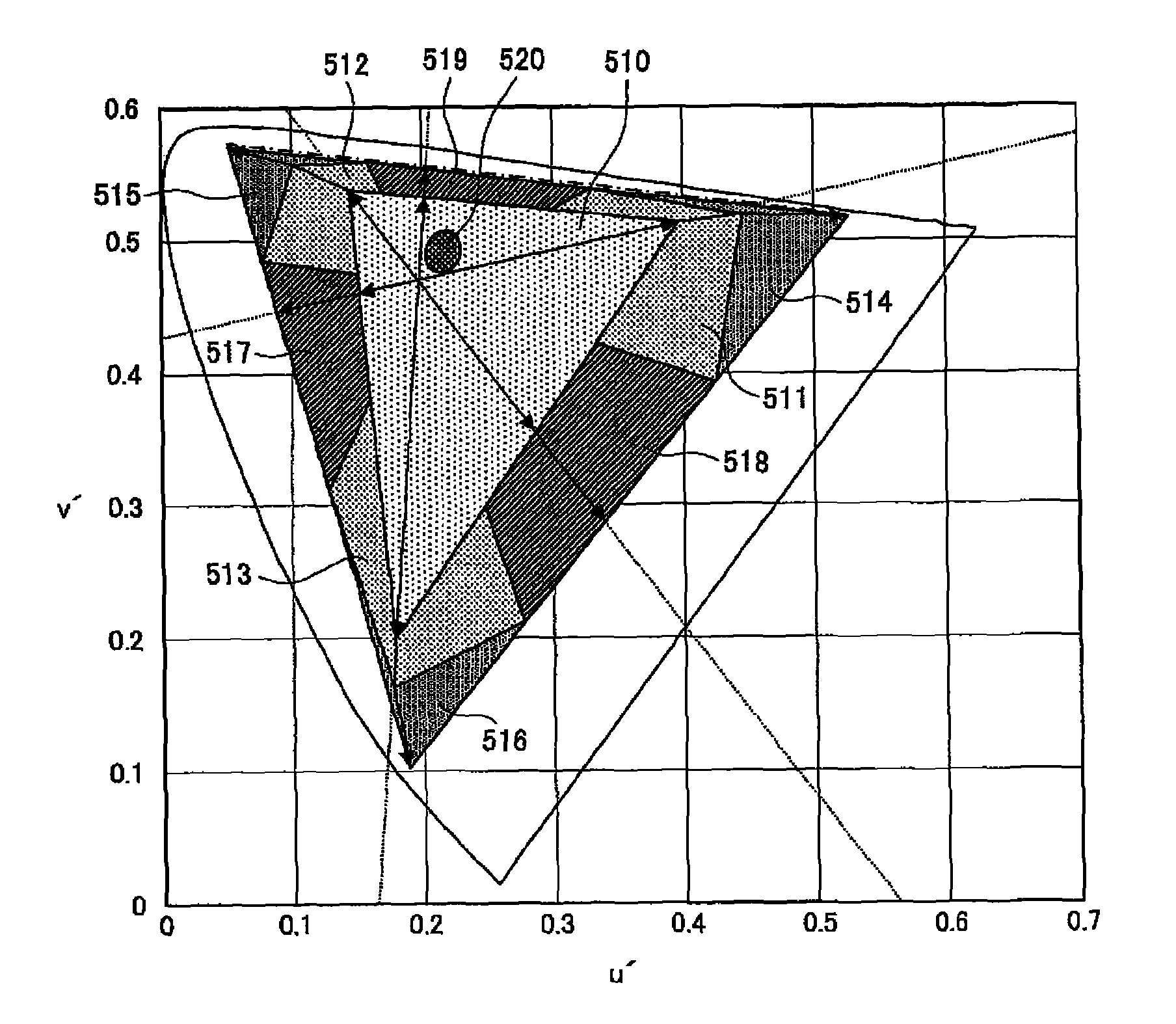
[0115]Although the first color space is divided into a plurality of color ranges and each color range is converted to the third color space in the first embodiment, the entire first color space is once converted to a virtual color space (hereinafter, fourth color space) larger than the second color space of the display device and the third color space is defined as a color space converted from the fourth color space so as to fall within the second color space in this embodiment.
[0116]A specific method of defining the third color space will be described belo...
third embodiment
[0141]A third embodiment of the present invention will then be described.
[0142]In the second embodiment, the sums of positive elements of the lines of Eq. 26 indicate how many times of the emission before the conversion corresponds to the maximum emission of red / blue / green LEDs after the conversion. Therefore, it is desirable that each of the sums is one for every LED. Since the sum of the first line corresponding to red is 0.828 in Eq. 26, a value greater than 0.828×255 does not appear after the conversion in red and green for any input video signal in this example, and the dynamic range of the color image displaying portion 13 is narrowed. The sum of positive elements of each line may be approximated to one to expand the dynamic range by individually changing the maximum emission amounts of the LEDs.
[0143]If the LED drive current is increased to increase an emission amount, a signal value of color corresponding to the LED may be reduced when a certain color is displayed. Therefore...
PUM
 Abstract
Description
Claims
Application Information
 - R&D
- Intellectual Property
- Life Sciences
- Materials
- Tech Scout
- Unparalleled Data Quality
- Higher Quality Content
- 60% Fewer Hallucinations
Browse by: Latest US Patents, China's latest patents, Technical Efficacy Thesaurus, Application Domain, Technology Topic, Popular Technical Reports.
© 2025 PatSnap. All rights reserved.Legal|Privacy policy|Modern Slavery Act Transparency Statement|Sitemap|About US| Contact US: help@patsnap.com


