Surface light source device and image display apparatus

a technology of surface light source and image display, which is applied in the direction of lighting and heating apparatus, instruments, lenses, etc., can solve the problems of increasing non-uniformity in brightness, and achieve the effects of improving brightness and transmittance near the region directly in front of the light source, reducing the thickness of the apparatus, and suppressing non-uniformity in brightness

Inactive Publication Date: 2009-07-23
SONY CORP
View PDF5 Cites 4 Cited by
  • Summary
  • Abstract
  • Description
  • Claims
  • Application Information

AI Technical Summary

Benefits of technology

[0031]Therefore, the brightness and transmittance near regions directly in front of the light source are improved. Consequently, the brightness at the regions directly in front of the light source and the brightness near the regions directly in front of the light source are made substantially uniform, whereby reduction of the thickness of the apparatus and suppression of nonuniformity in brightness can be realized simultaneously.

Problems solved by technology

If it is attempted to reduce the thickness of such an apparatus by reducing the interval between the light source and the diffusing member, a problem arises in that the existence of lamps may be recognized as a lamp image, as described above.
This leads to a problem in that nonuniformity in brightness increases.

Method used


Image

  • Surface light source device and image display apparatus
  • Surface light source device and image display apparatus
  • Surface light source device and image display apparatus

Examples


Embodiment Construction

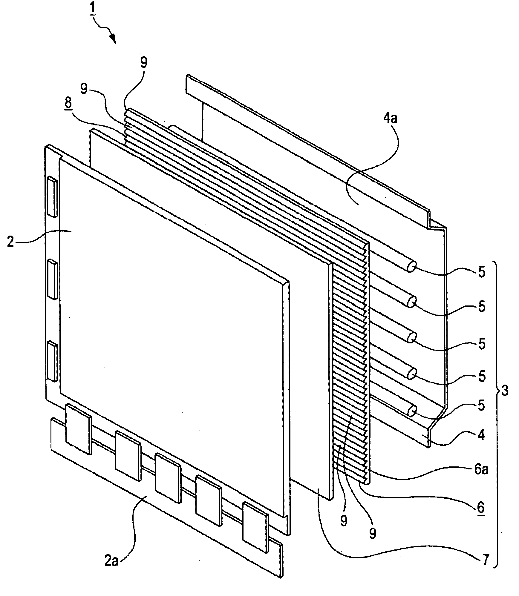
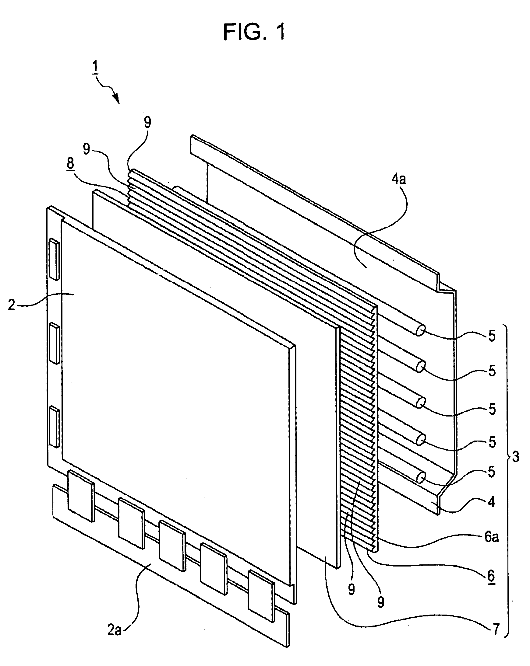
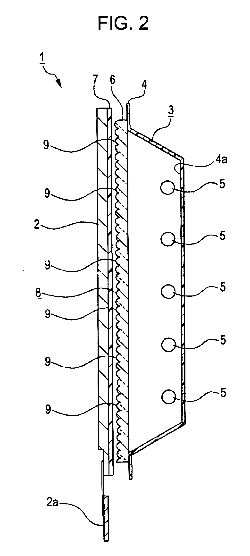
[0042]Embodiments of the surface light source device and the image display apparatus according to the present invention will now be described with reference to the accompanying drawings.

[0043]The embodiments described hereinafter concern a case where the image display apparatus and the surface light source device of the present invention are applied to a television receiver that displays an image on a liquid crystal panel and a surface light source device included in the television receiver, respectively.

[0044]The scope of the present invention is not limited to such a television receiver having a liquid crystal panel and a surface light source device included therein, and may be widely applied to any of other television receivers and image display apparatuses used with personal computers, and any of other surface light source devices included in such apparatuses.

[0045]Referring to FIGS. 1 and 2, an image display apparatus (television receiver) 1 includes relevant elements housed in...


PUM


Abstract

A surface light source device includes a light source facing a reflective surface of a reflecting member, and a light-controlling member composed of a transparent material and disposed across the light source from the reflecting member in such a manner as to face the reflective surface, the light-controlling member guiding light emitted from the light source in a predetermined direction. The light-controlling member has on a surface thereof remote from the reflective surface projections arranged on a plane. The projections have profiles of at least one kind, each having a symmetry axis or a symmetry plane. The symmetry axes or the symmetry planes of the projections are tilted at a predetermined angle with respect to a direction in which the light controlling member faces the reflecting member.

Description

CROSS REFERENCES TO RELATED APPLICATIONS[0001]The present invention contains subject matter related to Japanese Patent Application JP 2008-012574 filed in the Japanese Patent Office on Jan. 23, 2008, the entire contents of which are incorporated herein by reference.BACKGROUND OF THE INVENTION[0002]1. Field of the Invention[0003]The present invention relates to technical fields of surface light source devices and image display apparatuses. In particular, the present invention relates to a technical field for reducing the thickness of such a device and an apparatus and for suppressing nonuniformity in brightness thereof by providing projections having predetermined shapes, to a light-controlling member that controls light emitted from a light source.[0004]2. Description of the Related Art[0005]There are surface light source devices in which light sources such as cold-cathode fluorescent lamps (CCFLs) or light-emitting diodes (LEDs) are used for illumination. Such a surface light sourc...

Claims


Application Information

Patent Timeline
Patent Type & Authority Applications(United States)
IPC IPC(8): G09F13/08F21V7/00
CPCG02B3/0006G02B5/0215G02B5/0221G02F2001/133607G02B5/0278G02B5/208G02B5/0242G02F1/133607
Inventor ITO, ATSUSHIKOUYAMA, YOSHIAKI
Owner SONY CORP
Why Eureka
Try Eureka