Method and apparatus for predicting braking system friction

Inactive Publication Date: 2009-07-23
GM GLOBAL TECH OPERATIONS LLC
View PDF25 Cites 52 Cited by
  • Summary
  • Abstract
  • Description
  • Claims
  • Application Information

AI Technical Summary

Benefits of technology

[0013]In another aspect of the invention, a vehicle has a braking system having a set of front brake rotors, a set of rear brake rotors, a hydraulic braking mechanism, and an electronic braking mechanism which may be operatively combined to form a blended braking event, and a controller having a control algorithm and a neural

Problems solved by technology

However, the difficulty in precisely combining conventional friction braking and electronic braking t

Method used


Image

  • Method and apparatus for predicting braking system friction
  • Method and apparatus for predicting braking system friction
  • Method and apparatus for predicting braking system friction

Examples


Embodiment Construction

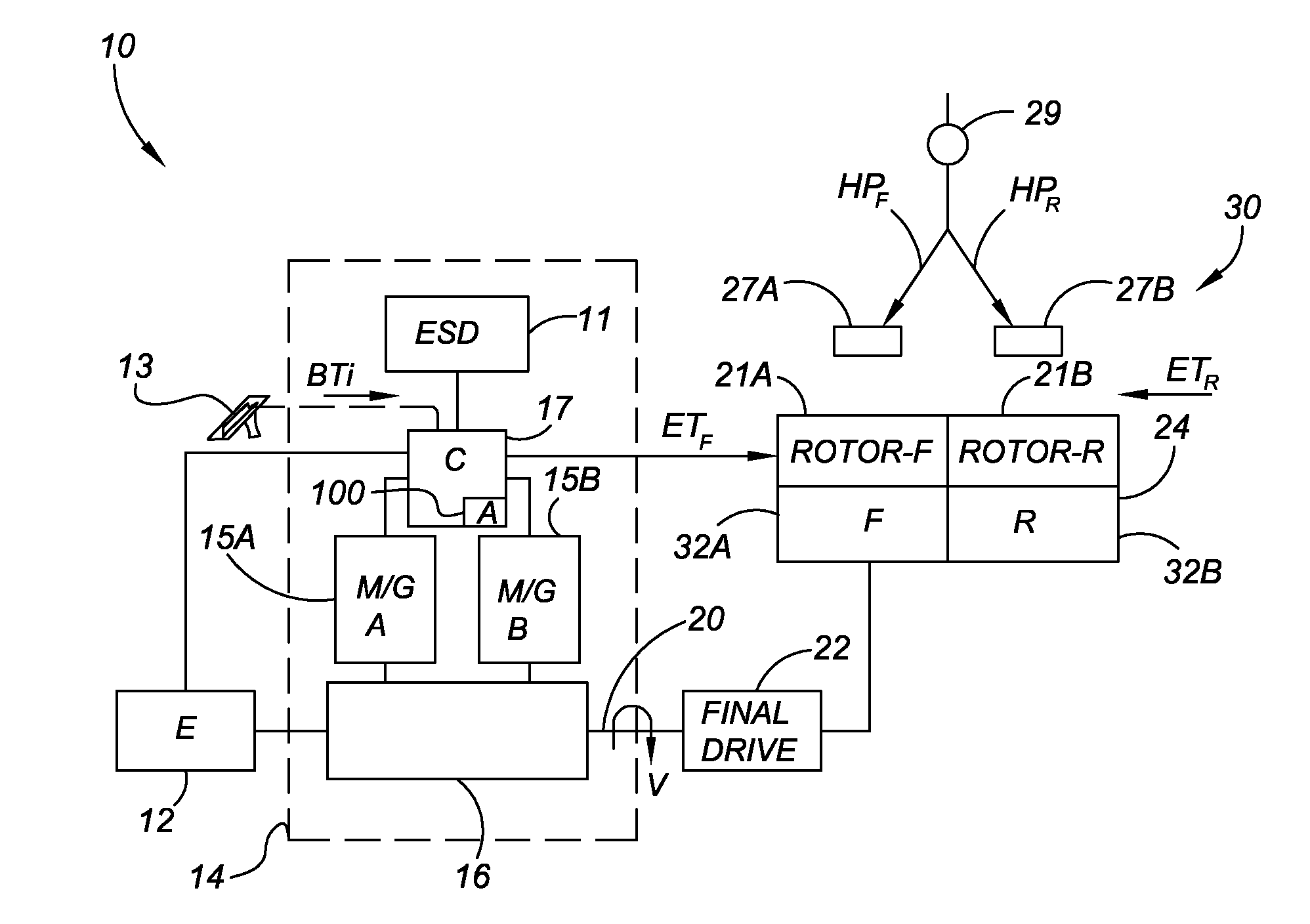
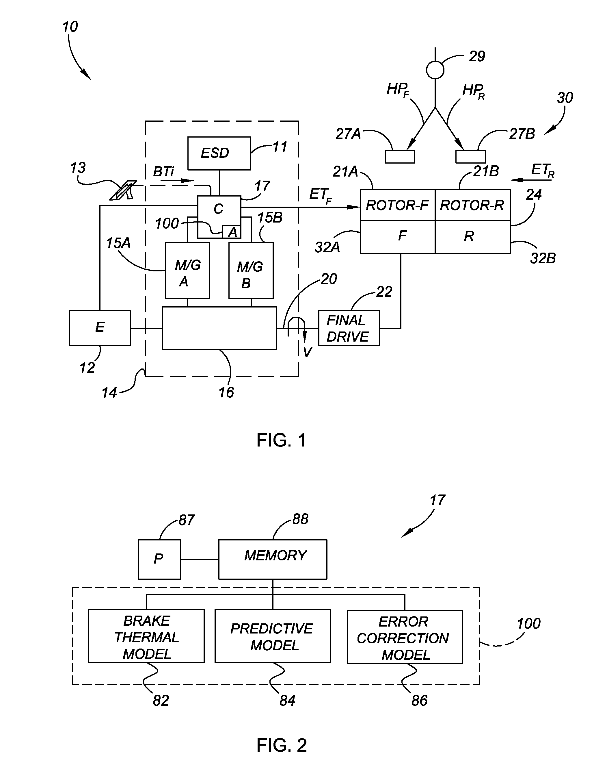
[0020]Referring to the drawings, wherein like reference numbers correspond to like or similar components throughout the several figures, and beginning with FIG. 1, a vehicle 10 includes an engine 12, such as an internal combustion engine, fuel cell, or another motive device suitable for providing energy for propelling the vehicle 10. The engine 12 is in driving connection with at least one gear set 16 of a transmission 14 for powering a plurality of wheels 24. The wheels 24 include a set of front wheels 32A, also labeled “F” in FIG. 1, and a set of rear wheels 32B, also labeled “R” in FIG. 1, with each set of wheels 32A, 32B having a respective brake rotor 21A, 21B.

[0021]The transmission 14 is configured in one embodiment as a hybrid transmission as shown, and therefore the vehicle 10 may be selectively propelled using the engine 12 and / or either or both of a pair of electric motor / generators 15A and 15B, also respectively labeled M / G A and M / G B. The transmission 14 includes an ele...


PUM


Abstract

A brake system control method determines vehicle operating conditions, compares the conditions to an allowable range, and uses a neural network to predict an expected coefficient of friction when the conditions are within the range. When the conditions fall outside of the range, the method determines an amount of required braking force using a constant coefficient of friction, and calculates the required braking force using the expected coefficient of friction when the conditions are within the range. The vehicle operating conditions include a vehicle speed, brake pressure, modeled brake rotor temperature, and apply state. The expected coefficient is multiplied by a constant or a calculated correction factor. A vehicle has an engine, transmission, and braking system, with a controller and an algorithm for predicting a coefficient of friction for two brake rotors, calculating a hydraulic brake pressure, and for applying the braking system using the hydraulic brake pressure.

Description

TECHNICAL FIELD[0001]The invention relates generally to a method and apparatus for optimizing or smoothing a blended braking event in a vehicle braking system that is operable for combining electronic or regenerative powertrain braking torque with conventional frictional braking to achieve a desired rate of deceleration, and in particular to a method and apparatus utilizing both a neural network model for predicting an expected braking friction value and an adaptive model for adjusting an output of the neural network model in response to a calculated system error.BACKGROUND OF THE INVENTION[0002]Conventional automotive vehicles typically include a brake pedal that is operatively connected to a brake lever or arm. The motion of the brake arm in turn actuates a braking mechanism to thereby slow and / or stop the vehicle, typically using an applied hydraulic pressure. For example, stepping on a brake pedal exerts a force on a master cylinder, which then pressurizes various hydraulic line...

Claims


Application Information

Patent Timeline
IPC IPC(8): B60T8/172
CPCB60T8/172B60T13/74B60T13/662B60T8/174B60L3/0076B60L7/26B60L15/2009B60L2240/12B60L2240/421B60L2240/423B60L2240/425B60L2240/80B60L2250/26B60L2260/42B60L2260/46B60L2260/50Y02T10/72B60L50/61B60L50/16B60L58/40Y02T10/62Y02T10/64Y02T10/7072Y02T10/70Y02T90/40
Inventor ANTANAITIS, DAVID B.YANG, CHIA N.
Owner GM GLOBAL TECH OPERATIONS LLC
Why Eureka
Try Eureka