

Feed source device and microwave antenna
A microwave antenna and feed source technology, applied in the direction of antennas, electrical components, etc., can solve the problems of high standing wave ratio of antennas and restrictions on the selection of dielectric materials, and achieve the effect of reducing reflection, reducing restrictions, and eliminating the deterioration of standing wave ratio
- Summary
- Abstract
- Description
- Claims
- Application Information
AI Technical Summary
Problems solved by technology
Method used
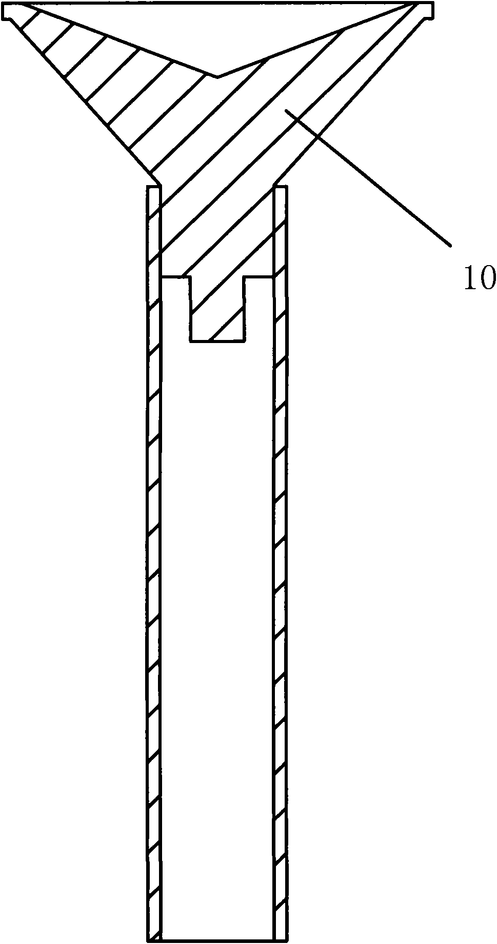
Image

Examples
Embodiment Construction
[0017] In order to make the object, technical solution and advantages of the present invention clearer, the present invention will be further described in detail below in conjunction with the accompanying drawings and embodiments. It should be understood that the specific embodiments described here are only used to explain the present invention, not to limit the present invention.
[0018] In the embodiment of the present invention, through the added matching medium, the reflection of the electromagnetic wave on the outer surface of the dielectric can be greatly reduced, thereby basically eliminating the deterioration of the standing wave ratio caused by the reflected wave on the outer surface of the dielectric, and also reducing the dielectric in the Material selection restrictions. .
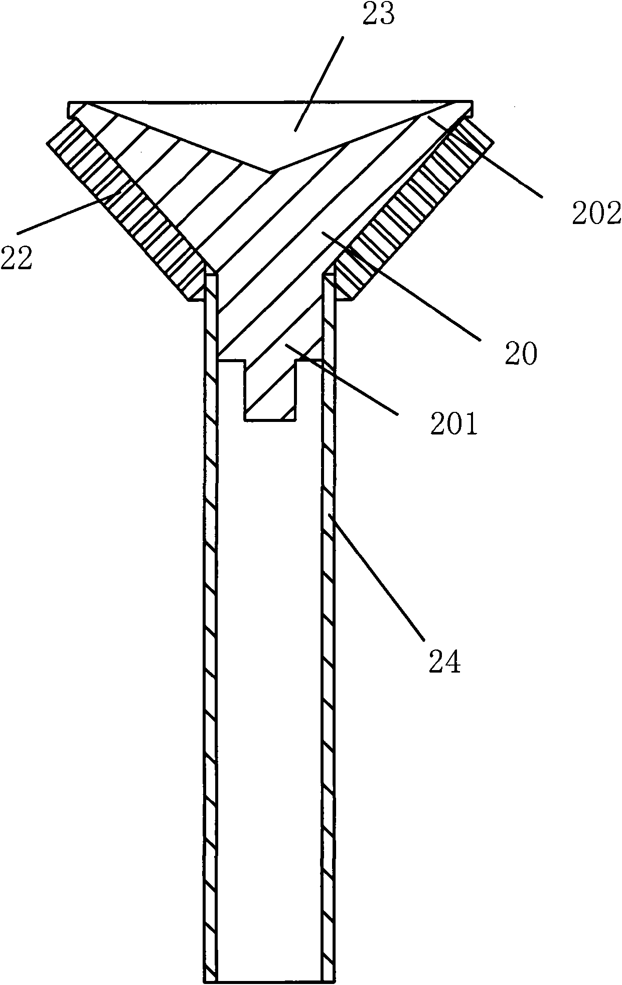
[0019] see figure 2 , the feed device provided by the embodiment of the present invention includes:
[0020] waveguide 24;
[0021] a dielectric 20 inserted at one end of the waveguide 24...
PUM
 Abstract
Description
Claims
Application Information