Brake hydraulic pressure control device

a control device and hydraulic pressure technology, applied in the direction of brake components, vehicle components, braking systems, etc., can solve the problem of increasing the dimension of the entire device, and achieve the effect of reducing the space for wiring conductive members and decreasing the number of conductive members

Inactive Publication Date: 2009-07-30
ADVICS CO LTD
View PDF8 Cites 18 Cited by
  • Summary
  • Abstract
  • Description
  • Claims
  • Application Information

AI Technical Summary

Benefits of technology

[0008]Accordingly, it is a primary object of the present invention to provide an improved brake hydraulic pressure control device which can be down...

Problems solved by technology

This needs a space for wiring many conductive members, and this gives rise to a problem that t...

Method used


Image

  • Brake hydraulic pressure control device
  • Brake hydraulic pressure control device
  • Brake hydraulic pressure control device

Examples


Embodiment Construction

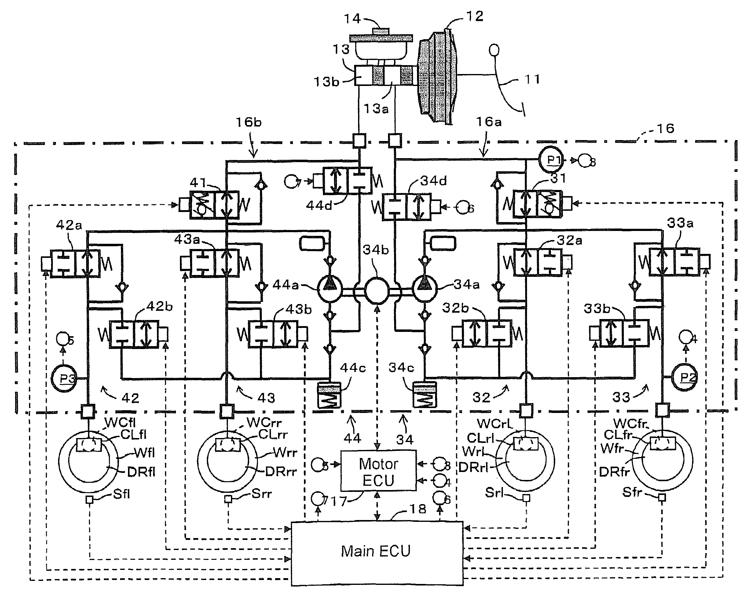
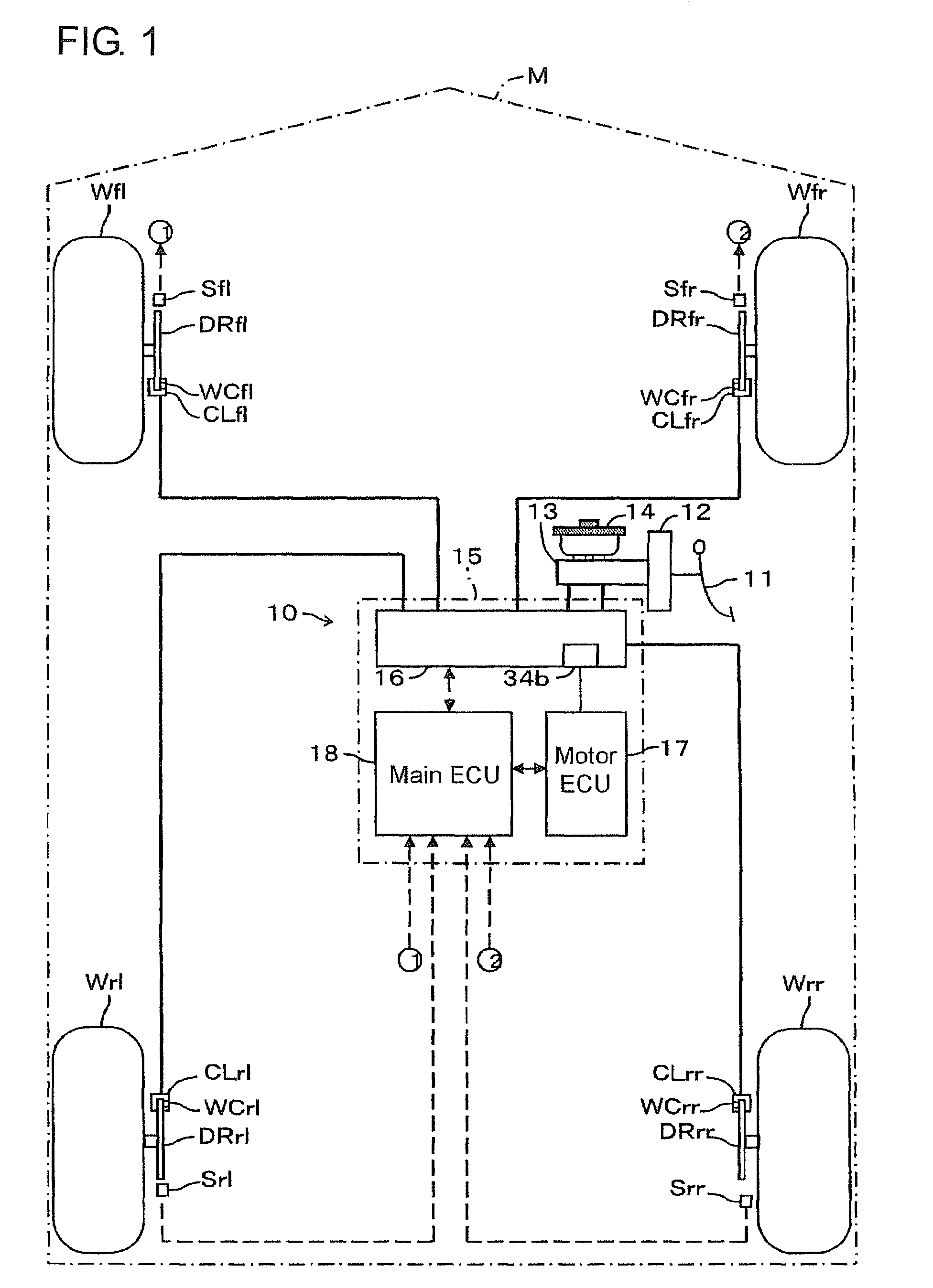
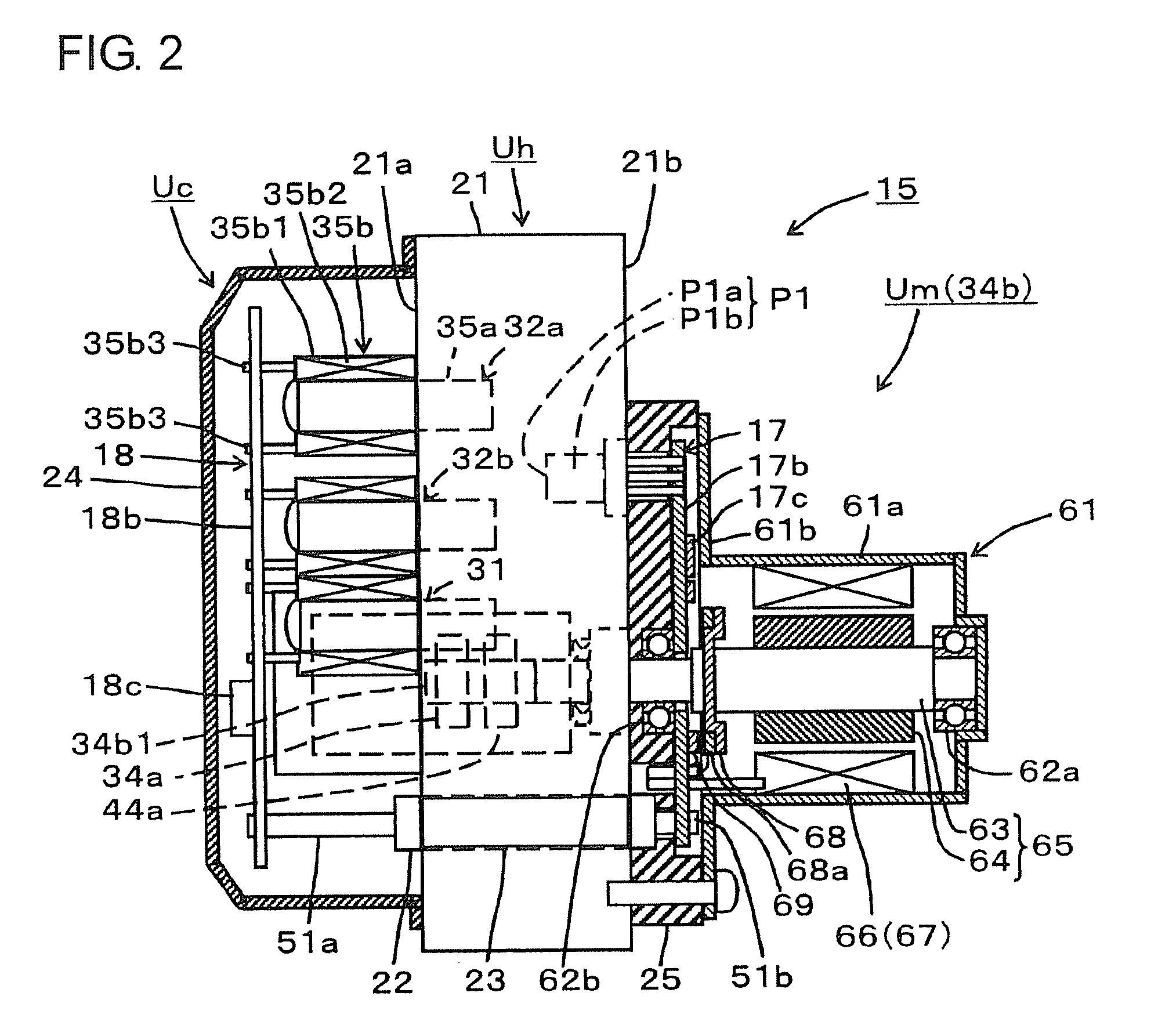
[0018]Hereafter, a vehicle incorporating a brake hydraulic pressure control device in one embodiment according to the present invention will be described with reference to the accompanying drawings. FIG. 1 is a schematic view showing the construction of a vehicle M, FIG. 2 is a front view partly in section of the brake hydraulic pressure control device 15, and FIG. 3 is a hydraulic circuit diagram showing a hydraulic brake device 10 of the vehicle M.

[0019]The hydraulic brake device 10 is for applying hydraulic brake forces to respective wheels Wfl, Wfr, Wrl, Wrr to brake the vehicle M. The hydraulic brake device 10 is provided with wheel cylinders WCfl, WCfr, WCrl, WCrr for respectively restricting rotations of the respective wheels Wfl, Wfr, Wrl, Wrr, a brake pedal 11, and a vacuum booster 12 as boosting device for assisting and boosting (augmenting) a braking manipulation force generated upon the stepping manipulation of the brake pedal 11 by applying an intake vacuum pressure fro...


PUM


Abstract

In a brake hydraulic pressure control device, a main ECU is provided with a first converter for converting serial signals or parallel signals inputted thereto into parallel signals or serial signals to output the converted signals, while a motor ECU arranged away from the main ECU is provided with a second converter for converting serial signals or parallel signals inputted thereto into parallel signals or serial signals to output the converted signals. The first and second converters are electrically connected with each other through at least one conductive member capable of serial communication.

Description

INCORPORATION BY REFERENCE[0001]This application is based on and claims priority under 35 U.S.C. 119 with respect to Japanese Applications No. 2008-014305 and No. 2008-307249 respectively filed on Jan. 24 and Dec. 2, 2008, the entire contents of which are incorporated herein by reference.BACKGROUND OF THE INVENTION[0002]1. Field of the Invention[0003]The present invention relates to a brake hydraulic pressure control device for use in a brake system for vehicles.[0004]2. Discussion of the Related Art[0005]Heretofore, as brake hydraulic pressure control devices, there has been known one which is described in Japanese unexamined, published patent application No. 10-129445. As shown in FIG. 6 of the Japanese application, the brake hydraulic pressure control device is provided with a plurality of electromagnetic valves for regulating the hydraulic pressures applied to wheel cylinders for wheels of a vehicle and a housing (control housing 100) with a pump provided therein for increasing ...

Claims


Application Information

Patent Timeline
IPC IPC(8): B60T8/44B60T8/34H02P6/06H02P6/08
CPCB60T8/321B60T8/4872B60T8/368
Inventor ABE, TAIZOSAKAI, MORIHARUYOSHIJIMA, TETSUYA
Owner ADVICS CO LTD
Why Eureka
Try Eureka