Piezoelectric actuator provided with a displacement meter, piezoelectric element used therefor, and positioning device using a piezoelectric actuator

Inactive Publication Date: 2009-07-30
WIRELESS ACCESSORY RETAINING LLC +1
View PDF4 Cites 20 Cited by
  • Summary
  • Abstract
  • Description
  • Claims
  • Application Information

AI Technical Summary

Benefits of technology

[0037]The electrode portions of the piezoelectric element on which the resistors are provided are connected with the ground electrode, or have the same potential as the voltages applied to the resistors. Therefore, even when a resistor is provided on a base sheet made of an insulator, a potential difference between the electrode surface of the piezoelectric element and the resistor or a resistor connection electrode connected with the resistor does not substantially occur. Thus, even when a high voltage is applied to the piezoelectric element to be driven, a capacitance component is not substantially generated, with the result that a detection signal indicating the change in resistance value is not influenced by the capacitance component. When an insulation resistance of a base material is low, a leak current does not substantially flow. Therefore, the amount of strain of the piezoelect

Problems solved by technology

When the hysteresis or creep occurs, it is difficult to perform accurate positioning.
Thus, the detection signal of the strain gauges cannot be accurately measured because of the influence of the capacitance component.
Then, the high voltage is applied to the strain gauge or the displacement detection device co

Method used


Image

  • Piezoelectric actuator provided with a displacement meter, piezoelectric element used therefor, and positioning device using a piezoelectric actuator
  • Piezoelectric actuator provided with a displacement meter, piezoelectric element used therefor, and positioning device using a piezoelectric actuator
  • Piezoelectric actuator provided with a displacement meter, piezoelectric element used therefor, and positioning device using a piezoelectric actuator

Examples


embodiment 1

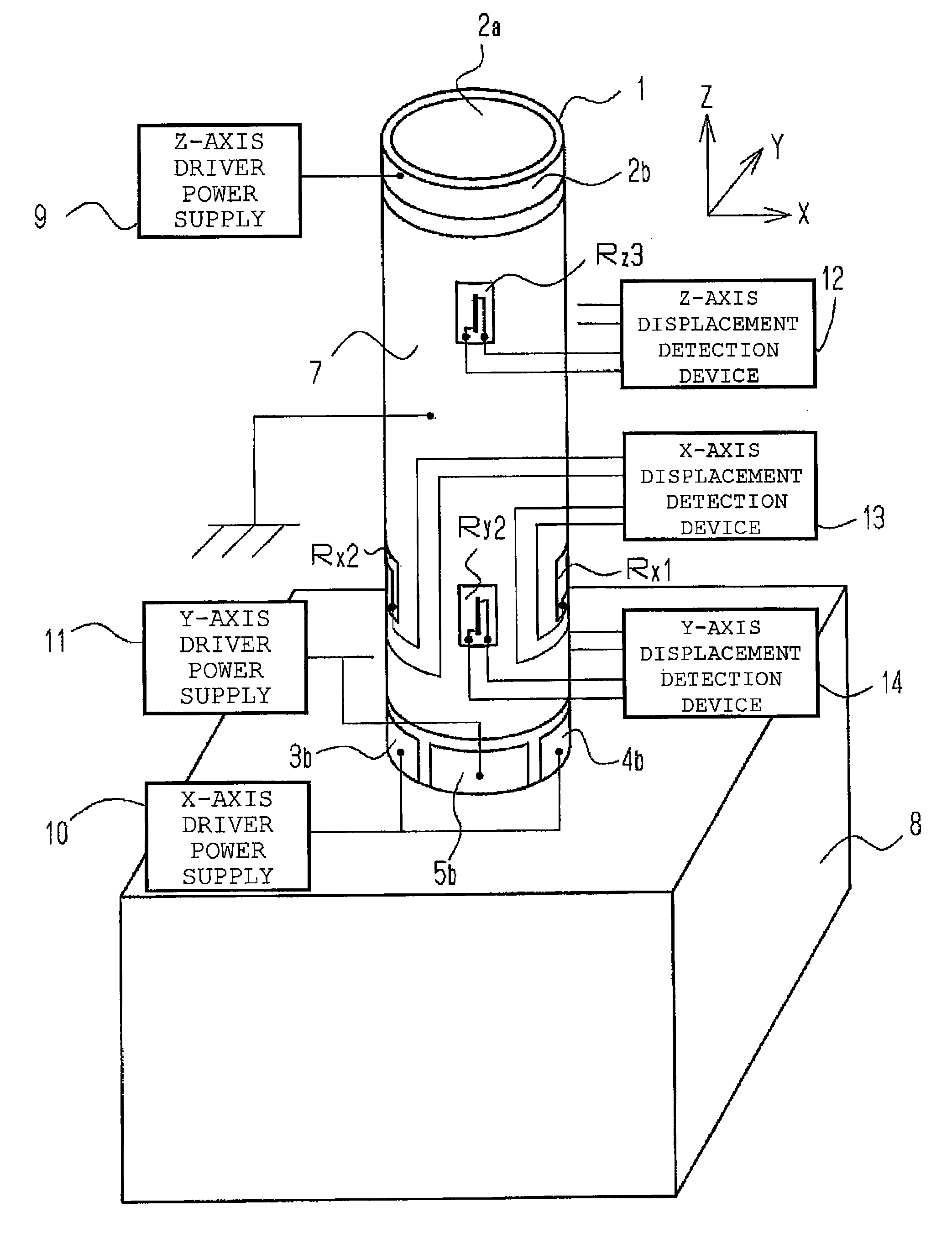
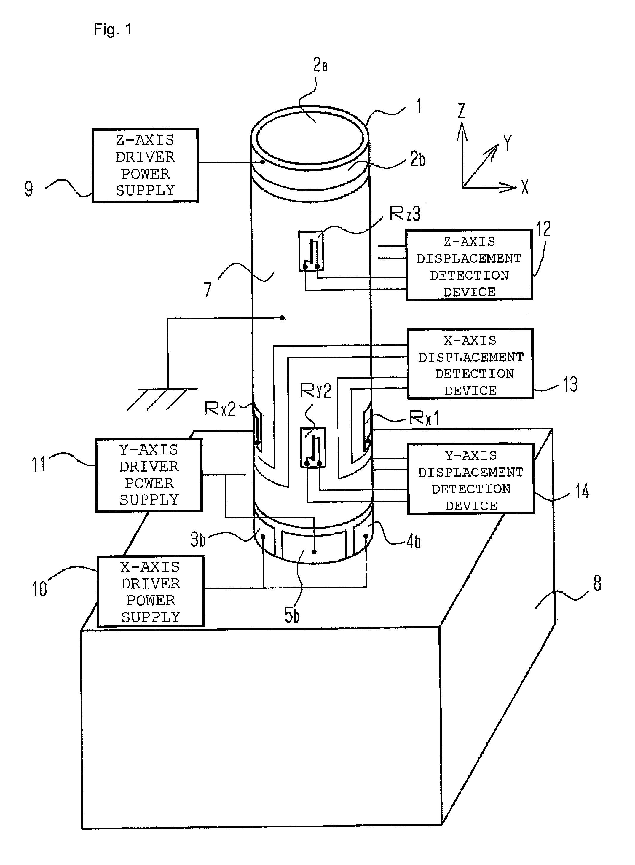
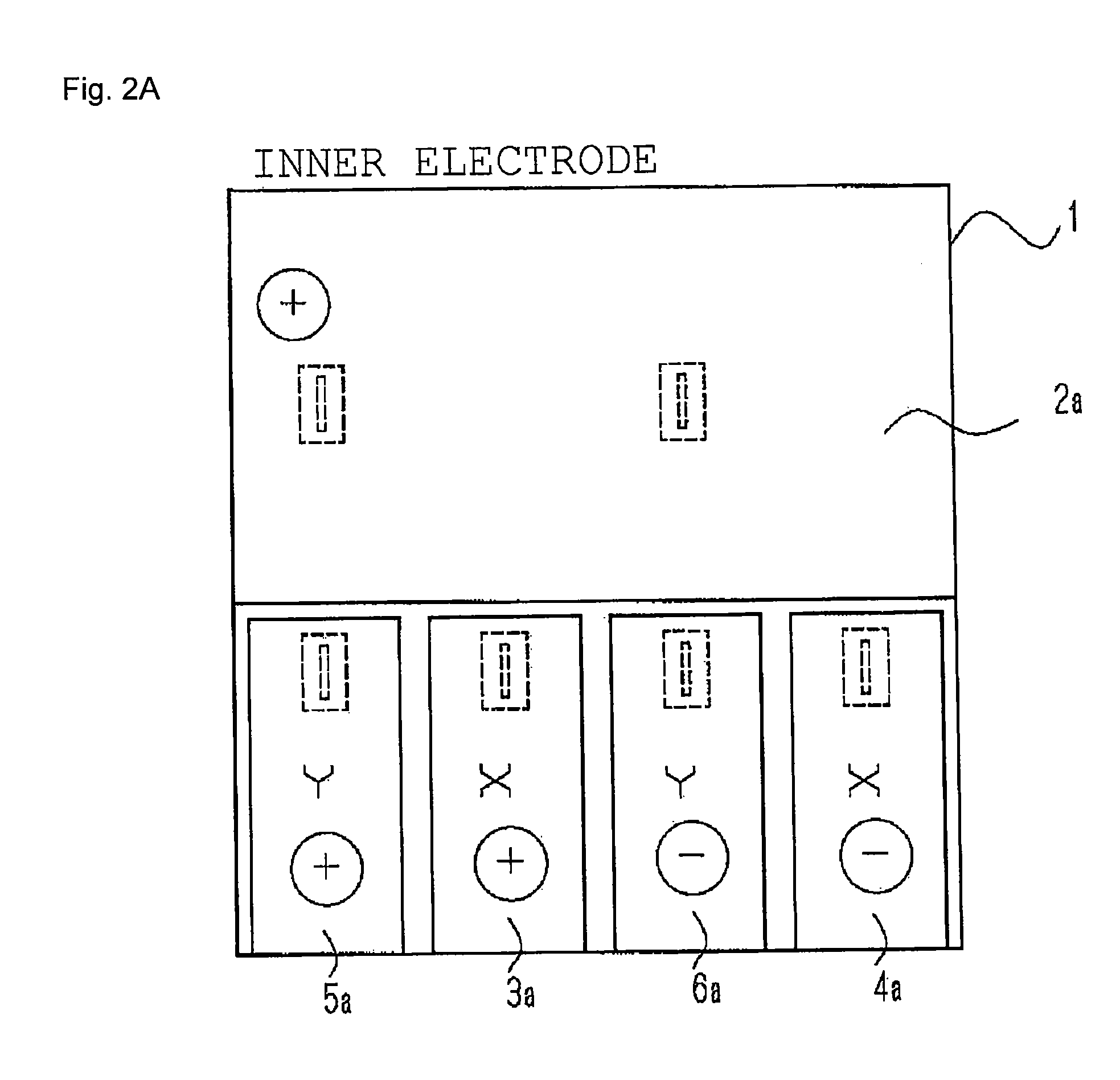
[0066]FIG. 1, FIGS. 2A and 2B, and FIGS. 3A and 3B illustrate a piezoelectric actuator provided with a displacement meter according to Embodiment 1 of the present invention. FIG. 1 is a schematic external view illustrating the piezoelectric actuator provided with a displacement meter. FIG. 2A is a developed view illustrating an inner surface of a cylindrical piezoelectric element used in FIG. 1. FIG. 2B is a developed view illustrating an outer surface of the cylindrical piezoelectric element.

[0067]In this embodiment, the cylindrical piezoelectric element as illustrated in FIG. 1 is used. In the cylindrical piezoelectric element 1, as illustrated in FIG. 2A, a band-shaped electrode portion 2a is uniformly provided in an upper portion of the inner surface along its circumference, and four-part electrode portions 3a, 4a, 5a, and 6a which are obtained by division into four parts along its circumference and formed in a direction parallel to a center axis of the cylinder are provided in ...

embodiment 2

[0099]FIGS. 9A and 9B illustrate a piezoelectric element 50 of a cylindrical piezoelectric actuator with a displacement meter according to Embodiment 2 of the present invention. FIG. 9A is a developed view illustrating an inner surface of the cylindrical piezoelectric element. FIG. 9B is a developed view illustrating an outer surface of the cylindrical piezoelectric element.

[0100]In this embodiment, four resistors are arranged for each axis. The four resistors serve as a bridge circuit, thereby improving measurement sensitivity and compensating for apparent strain of the resistors due to a change in temperature. In this embodiment, as illustrated in FIG. 9A, a folded electrode portion 51b connected with a band-shaped electrode portion 51a located on the outer surface as described later is provided in an upper end portion of the inner surface. A band-shaped electrode portion 52 is provided under the folded electrode portion 51b. Four-part electrode portions 53a, 54a, 55a, and 56a whi...

embodiment 3

[0112]FIGS. 10A and 10B illustrate a piezoelectric element 60 of a cylindrical piezoelectric actuator with a displacement meter according to Embodiment 3 of the present invention. FIG. 10A is a developed view illustrating electrodes located on an inner surface of the cylindrical piezoelectric element. FIG. 10B is a developed view illustrating electrodes located on an outer surface of the cylindrical piezoelectric element. The driving direction of the piezoelectric element and the displacement detection method are identical to those in Embodiments 1 and 2, and hence only the structure is described and the description of the operation is omitted.

[0113]In this embodiment, the cylindrical piezoelectric actuator with a displacement meter is an actuator for generating displacement in the direction parallel to the center axis. Band-shaped electrode portions 61b and 62a obtained by division into two parts in the vertical direction are provided on the inner surface.

[0114]The band-shaped elec...


PUM


Abstract

By resistor attached by a piezoelectric element, measurement with high accuracy is possible by strain of the piezoelectric element and there is not a trouble by a short, a piezoelectric actuator, the piezoelectric element and a positioning device therewith. The piezoelectric actuator includes; a piezoelectric element which is formed into an arbitrary shape, polarized in an arbitrary direction, and includes electrodes provided on at least two surfaces opposed in a thickness direction thereof; a driver power supply for applying a voltage between the electrodes to generate strain in the piezoelectric element; a driver power supply for applying a voltage to generate strain in the piezoelectric element; resistors provided on the electrodes through intermediation of insulators; and a displacement detection device connected with the resistors; The electrodes of the piezoelectric element on which the resistors are provided are set at a ground potential.

Description

RELATED APPLICATIONS[0001]This application claims priority under 35 U.S.C. § 119 to Japanese Patent Application Nos. JP2007-304798 filed on Nov. 26, 2007, and JP2008-278548 filed on Oct. 29, 2008, the entire contents of which are hereby incorporated by reference.BACKGROUND OF THE INVENTION[0002]1. Field of the Invention[0003]The present invention relates to a piezoelectric actuator used for, for example, a positioning device of a precision apparatus, and is applied to, for example, a scanner for a scanning probe microscope.[0004]2. Description of the Related Art[0005]Up to now, a piezoelectric actuator has been used for a precision positioning device with precision of the order of sub-nanometers to several hundred micrometers in various precision apparatuses including measurement apparatuses.[0006]Hereinafter, the positioning device using the piezoelectric actuator is described by way of example of a scanning probe microscope (see JP 09-089913 A).[0007]FIG. 22 is a structural diagra...

Claims


Application Information

Patent Timeline
IPC IPC(8): H01L41/00G01B7/16G01R27/08
CPCB82Y35/00G01B7/18G01Q10/04H01L41/042H01L41/083H01L41/092H01L41/094H01L41/04H10N30/80H10N30/802H10N30/2027H10N30/50
Inventor IYOKI, MASATO
Owner WIRELESS ACCESSORY RETAINING LLC
Why Eureka
Try Eureka