
Eureka
For R&D, Eureka makes reading and utilizing patents & technical documents easy.
Eureka AIR
Designed for self-driven R&D workflows. Generate viable solutions, solve complex R&D challenges, empower your innovation with AI.

Eureka Materials
Designed for material experts only. Revolutionize your material R&D, from search, analyze, to developing new materials.

TechResearch
Generate reliable direction feasibility study reports for your R&D in just a few steps.

TechSeek
Discover and master advanced knowledge NOW. Basics, ideas, possibilities, all at once.

TechMind
As an expert in R&D Theories, TechMind can generates customized viable solutions instantly.

TechRisk
Analyze your overall solution with one click, know your potential R&D risks in advance.

TechMonitor
Get weekly tech updates, stay abreast of the latest tech innovations and key insights.
Method for regulating a voltage and circuit therefor
- Summary
- Abstract
- Description
- Claims
- Application Information
AI Technical Summary
Problems solved by technology
Method used
Image

Examples
Embodiment Construction
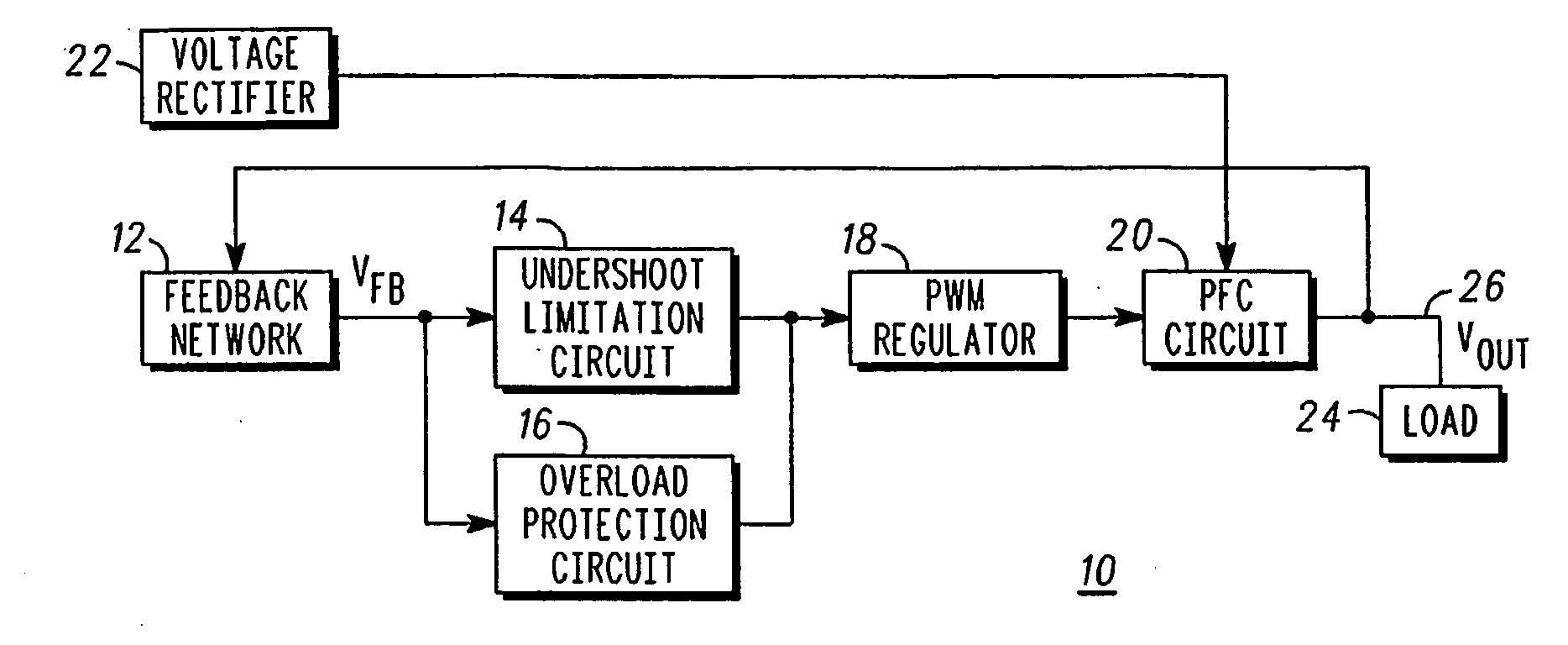
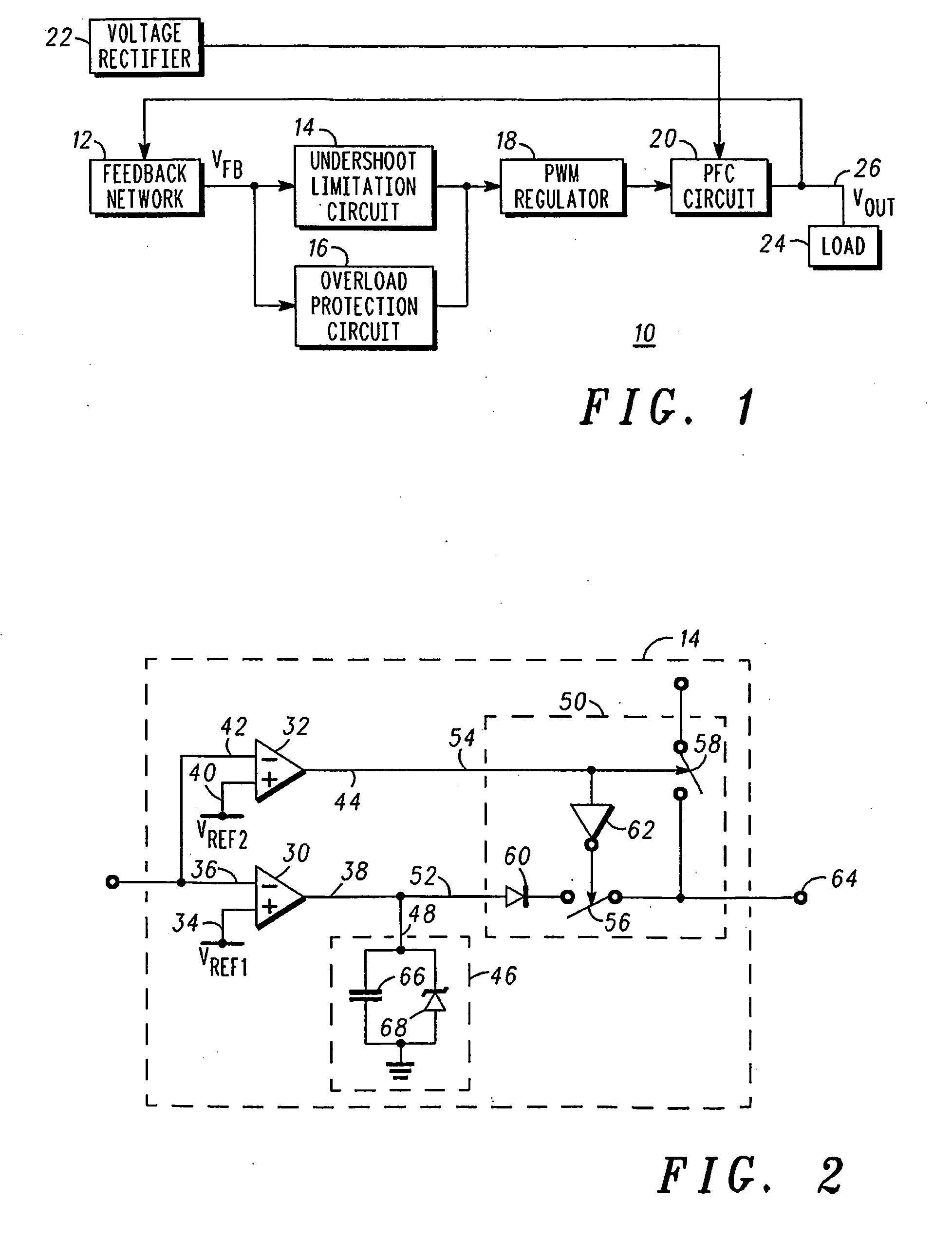
[0008]FIG. 1 is a block diagram of a voltage regulator 10 comprising a feedback network 12, an undershoot limitation circuit 14, an overload protection circuit 16, a switching or Pulse Width Modulated (“PWM”) regulation portion 18, a Power Factor Correction (“PFC”) circuit 20, and a voltage rectifier 22. More particularly, an input of undershoot limitation circuit 14 is connected to an output of feedback network 12 and an output of undershoot limitation circuit 14 is connected to an input of regulation portion 18. The output of feedback network 12 is also connected to the input of overload protection circuit 16 and the output of overload protection circuit 16 is connected to the input of regulation portion 18. The output of regulation portion 18 is connected to PFC circuit 20 and the output of PFC circuit 20 is connected to an input to feedback network 12 and to a load 24. Regulation portions and PFC circuits such as portion 18 and circuit 20, respectively, are known to those skille...
PUM
 Abstract
Description
Claims
Application Information
 - R&D Engineer
- R&D Manager
- IP Professional
- Industry Leading Data Capabilities
- Powerful AI technology
- Patent DNA Extraction
Browse by: Latest US Patents, China's latest patents, Technical Efficacy Thesaurus, Application Domain, Technology Topic, Popular Technical Reports.
© 2024 PatSnap. All rights reserved.Legal|Privacy policy|Modern Slavery Act Transparency Statement|Sitemap|About US| Contact US: help@patsnap.com