Synchronization of multiphase synthetic ripple voltage regulator

a voltage regulator and multi-phase technology, applied in the direction of dc-dc conversion, power conversion system, dc source parallel operation, etc., can solve the problems of output voltage overshoot, difficulty in maintaining tight dc regulation, and reducing power conversion efficiency

Inactive Publication Date: 2005-01-06
INTERSIL INC
View PDF5 Cites 52 Cited by
  • Summary
  • Abstract
  • Description
  • Claims
  • Application Information

AI Technical Summary

Benefits of technology

[0012] A multiphase synthetic ripple voltage generator for a multiphase DC-DC regulator according to an embodiment of the present invention includes a master clock circuit that generates a master clock signal, sequence logic and a ripple regulator for each phase or channel. The multiphase DC-DC regulator includes multiple switching circuits, each responsive to a corresponding pulse width modulation (PWM) signal to switch one or more input voltages via a corresponding phase node through a corresponding output inductor to collectively develop an output vol

Problems solved by technology

Since the hysteretic comparator directly sets the magnitude of the ripple voltage, employing a smaller hysteresis voltage reduces the power conversion efficiency, as switching frequency increases with smaller hysteresis.
Since the ripple voltage wave shape varies with input line and load conditions, maintaining tight

Method used


Image

  • Synchronization of multiphase synthetic ripple voltage regulator
  • Synchronization of multiphase synthetic ripple voltage regulator
  • Synchronization of multiphase synthetic ripple voltage regulator

Examples


Embodiment Construction

[0029] The following description is presented to enable one of ordinary skill in the art to make and use the present invention as provided within the context of a particular application and its requirements. Various modifications to the preferred embodiment will, however, be apparent to one skilled in the art, and the general principles defined herein may be applied to other embodiments. Therefore, the present invention is not intended to be limited to the particular embodiments shown and described herein, but is to be accorded the widest scope consistent with the principles and novel features herein disclosed.

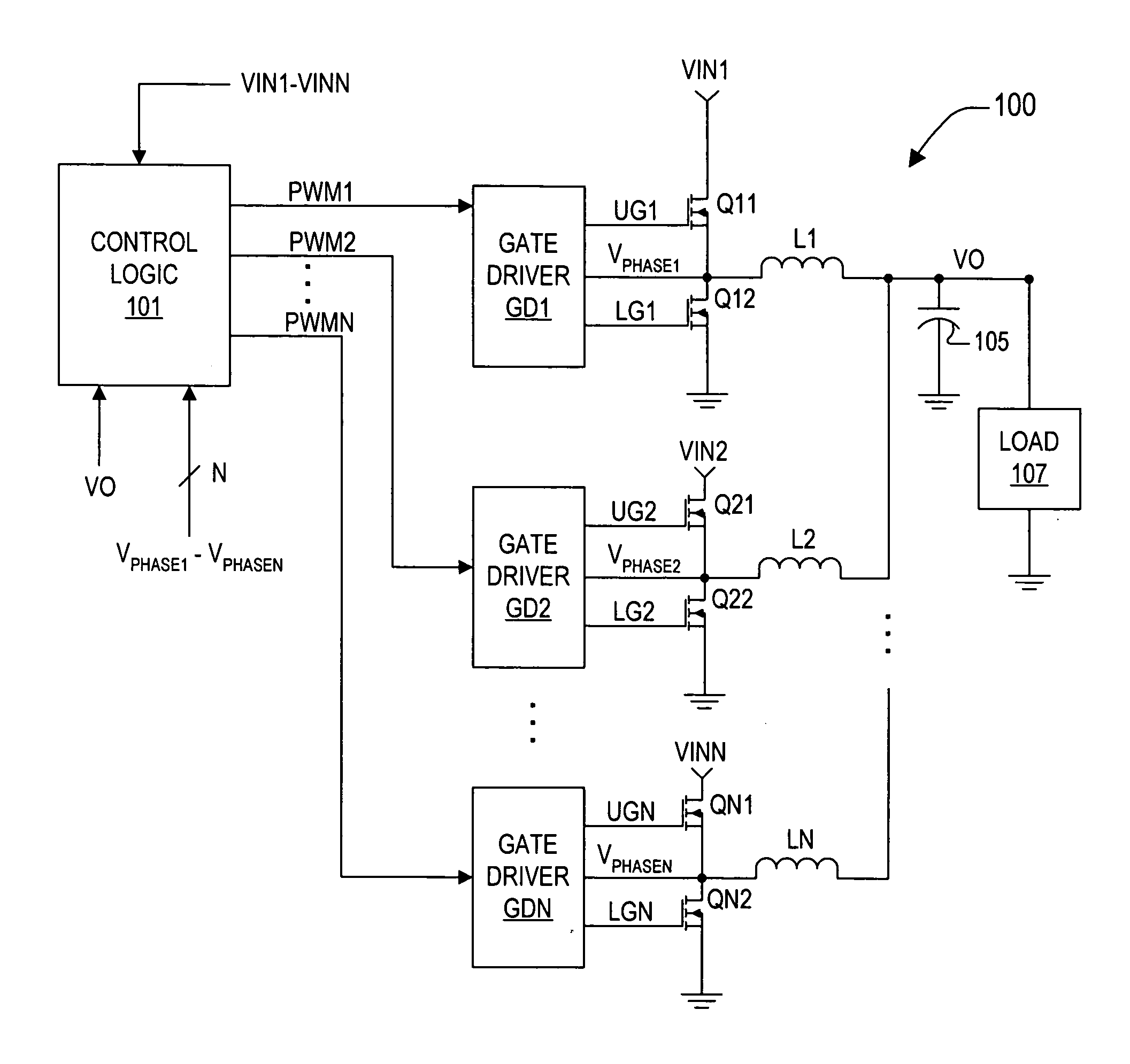
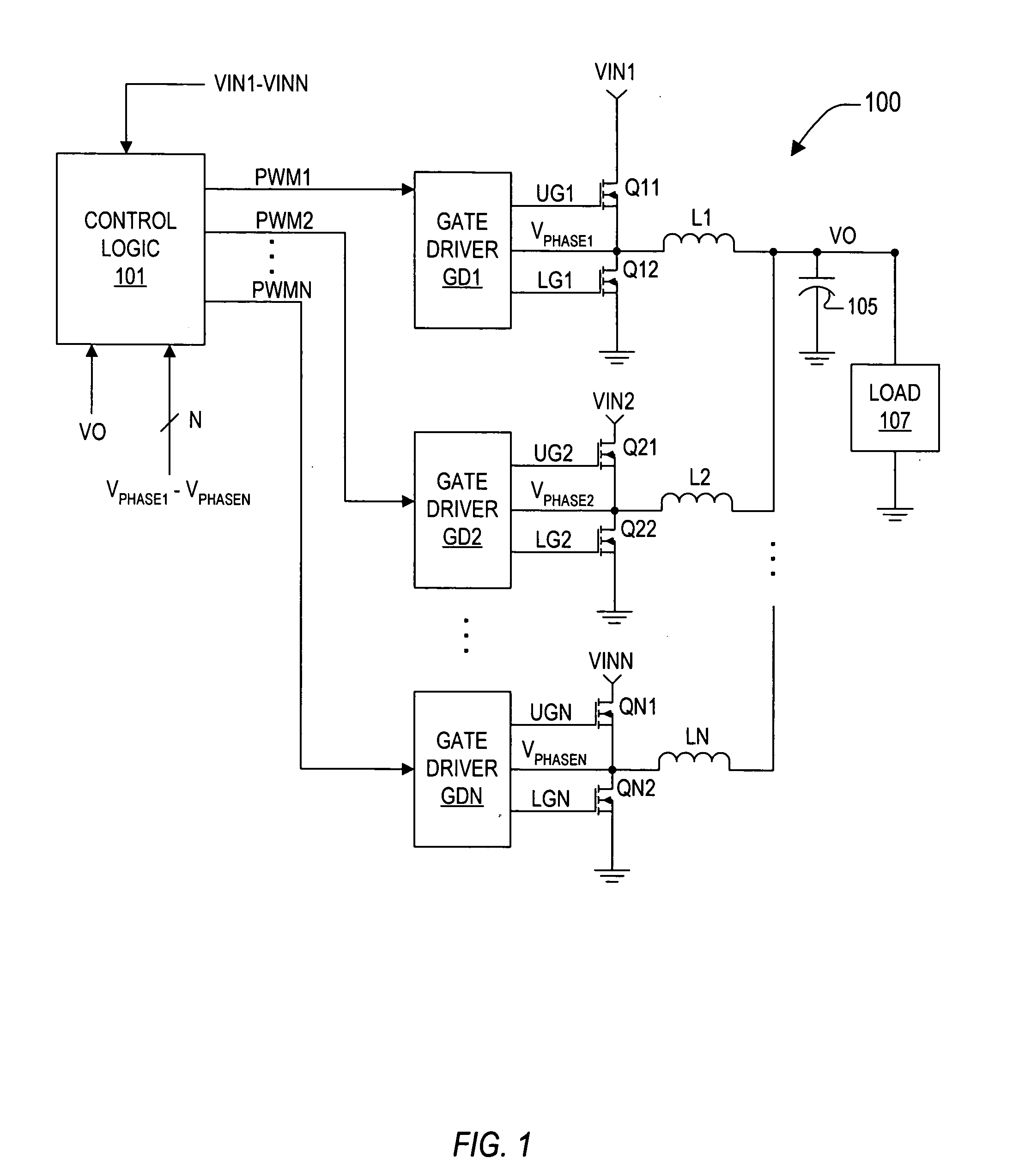
[0030]FIG. 1 is a simplified schematic and block diagram of a multiphase synthetic ripple voltage regulator 100 implemented according to an exemplary embodiment of the present invention. The multiphase regulator 100 includes a pulse width modulation (PWM) controller or a multiphase synthetic ripple voltage generator 101, which provides a number “N” of PWM signals PWM1, PWM2, ...


PUM


Abstract

A multiphase synthetic ripple voltage generator for a multiphase DC-DC regulator including a master clock circuit that generates a master clock signal, sequence logic and a ripple regulator for each phase. The DC-DC regulator includes multiple switching circuits, each responsive to a corresponding PWM signal to switch input voltages via a phase node through an output inductor to develop an output voltage. The sequence logic sets each PWM signal in sequential order based on the master clock signal. Each ripple generator includes a transconductance amplifier, a ripple capacitor and a comparator. The transconductance amplifier has an input coupled to a corresponding output inductor and an output coupled to a corresponding ripple capacitor. The comparator has a first input coupled to the ripple capacitor, a second input receiving an error voltage, and an output coupled to the sequence logic for resetting a corresponding PWM signal.

Description

CROSS-REFERENCE TO RELATED APPLICATIONS [0001] This application is a continuation-in-part (CIP) of copending and commonly assigned U.S. patent application Ser. No. 10 / 673,684, filed on Sep. 29, 2003, which itself is a CIP of copending and commonly assigned U.S. patent application Ser. No. 10 / 236,787 filed on Sep. 6, 2002, in which both are incorporated herein by reference for all intents and purposes.BACKGROUND OF THE INVENTION [0002] 1. Field of the Invention [0003] The present invention relates in general to power supply circuits and related components, and is particularly directed to an arrangement for synchronizing a plurality of synthetic ripple generators that generate artificial or synthesized ripple waveforms to control switching operations of a multiphase DC-DC synthetic ripple regulator. [0004] 2. Description of the Related Art [0005] Electrical power for integrated circuits is typically supplied by one or more direct current (DC) power sources. In a number of applications...

Claims


Application Information

Patent Timeline
IPC IPC(8): H02M3/155G05F1/40H02J1/10H02M3/156H02M3/158
CPCH02J1/102H02M3/1584H02M3/156G05F1/40
Inventor WALTERS, MICHAEL M.LI, XUENINGJOCHUM, THOMAS A.
Owner INTERSIL INC
Why Eureka
Try Eureka