Transfer Material Separating Device, Transfer Device and Image Forming Apparatus

Inactive Publication Date: 2009-07-30
SEIKO EPSON CORP
View PDF9 Cites 7 Cited by
  • Summary
  • Abstract
  • Description
  • Claims
  • Application Information

AI Technical Summary

Benefits of technology

[0009]The object of the present invention is to provide a transfer material separating device, a transfer device and an image forming apparatus that can reliably separate a transfer material without exerting any adverse influence on the image transferred onto the transfer material.
[0010]According to the present invention, the above object is achieved by providing a transfer material separating device, a transfer device and an image forming apparatus adapted to suck the second surface of a transfer material that is opposite to the first surface of the transfer material by means of a transfer material separation / sucktion section. Thus, the transfer material can be reliably separated from the transfer material moving member, which is an image carrier such as a transfer medium or a latent image carrier, as it is held in contact and moving with the transfer material moving member because it is being sucked. Then, as a result, the transfer material is prevented from moving with the transfer material moving member and reliably moved toward the next conveyance site. Additionally, since the transfer material is sucked at the second surface thereof that is opposite to the first surface, which is the transfer surface, the image transferred onto the transfer material is prevented from being adversely influenced by suction.
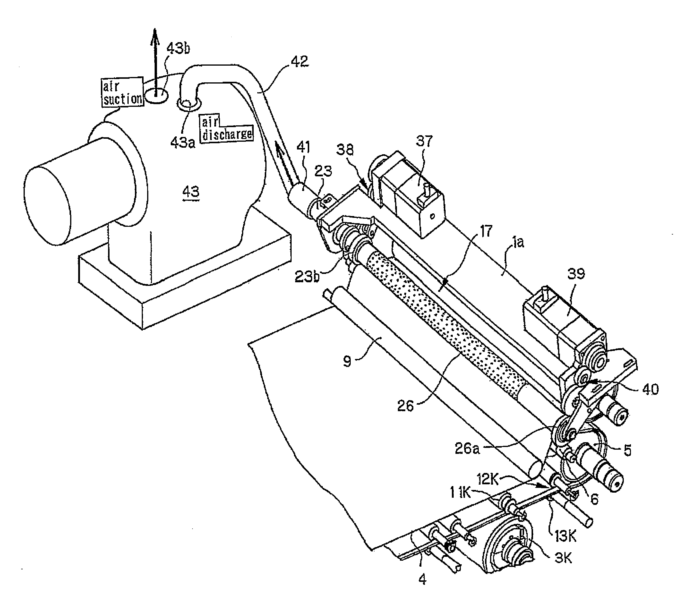
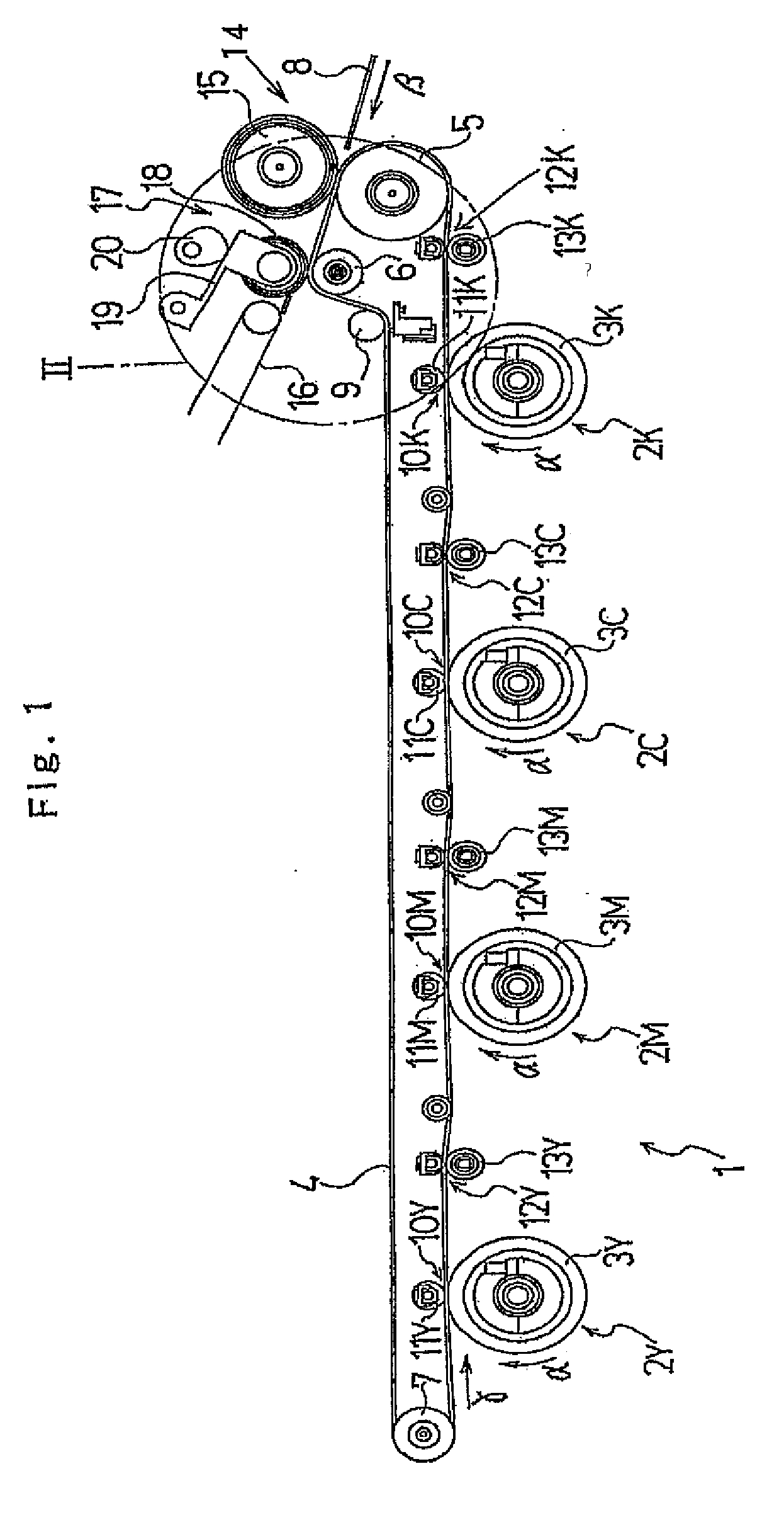
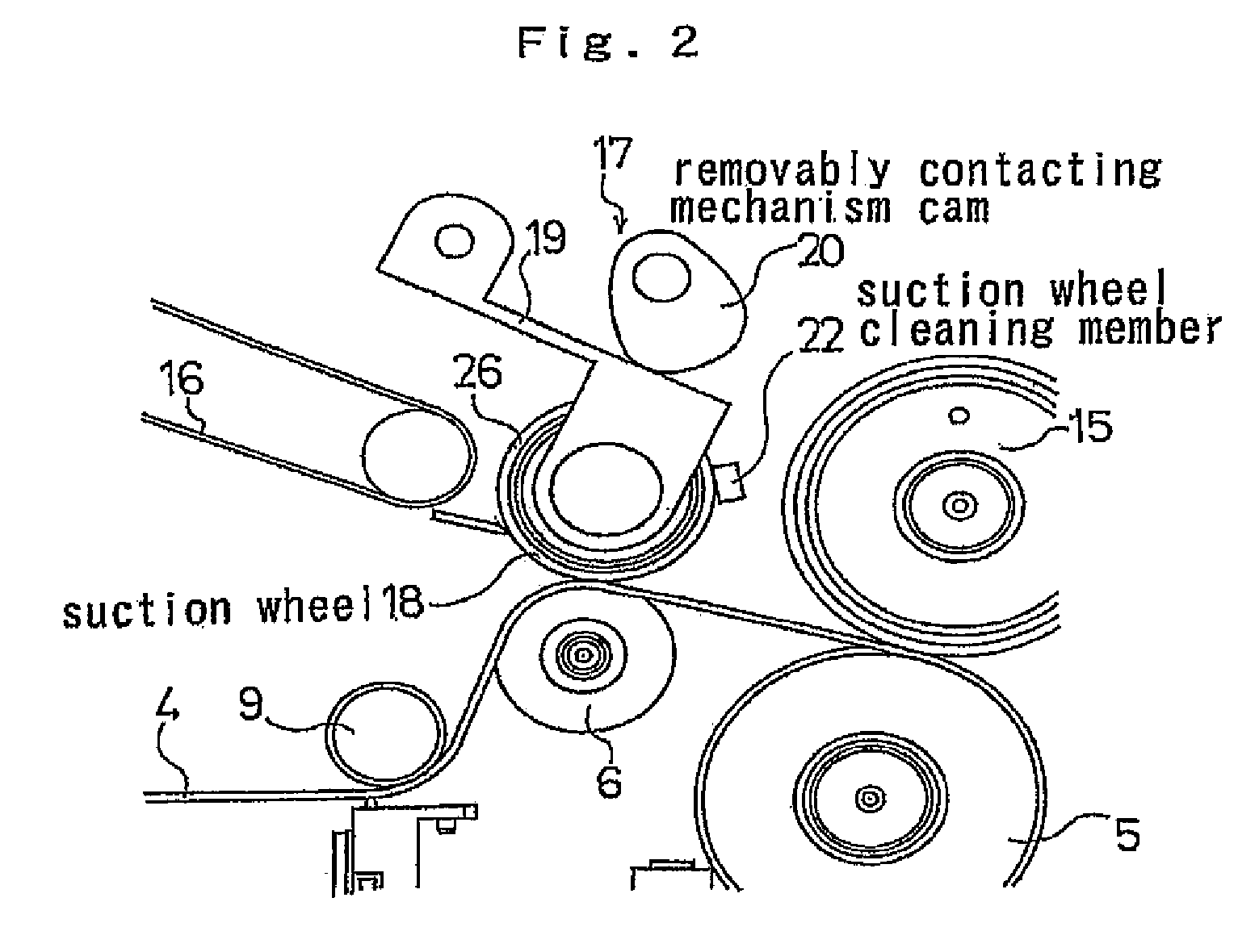
[0011]Particularly, a suction member is adapted to be brought into contact with or separated from the transfer material moving member such that the suction member can be held in contact with the transfer material moving member only when the transfer material is being conveyed and separated from the transfer material moving member when the transfer material is not being conveyed. Therefore, any residual toner and foreign objects such as dust can be prevented from adhering to the suction member from the transfer material moving member. Thus, as a result, any possible smearing of the transfer material when it is being sucked can be effectively suppressed.
[0012]Still additionally, the suction member includes a suction port side member having a suction port that is arranged to face the transfer material being conveyed when the suction wheel outer ring of the suction member is brought into contact with the transfer material moving member. Besides, the suction wheel outer ring is provided with through holes. Thus, air is sucked in by way of the through holes of the suction wheel outer ring that are arranged vis-a-vis the suction ports. Therefore, the suction member can constantly suck the transfer material in a sucking operation regardless if the suction wheel outer ring is rotated as the transfer material and the transfer material moving member move. Additionally, since air is sucked through the small suction port that constantly faces the transfer material during the sucking operation and has a relatively small capacity, the transfer material sucking power can be effectively secured to such a level that the transfer material is reliably separated from the transfer material moving member. Then, the capacity of the sucking section can be reduced so much. Still additionally, since the transfer material is not sucked by the suction wheel outer ring once it is moved away from the suction port, the transfer material can be smoothly moved to the next conveyance site.
[0013]Furthermore, as the suction wheel outer ring rotates in a state where the vacuum wheel taking in air, the suction port side member rotates to a predetermined extent in the sense of rotation of the suction wheel outer ring. Then, as a result, the transfer material can be conveyed to the guide position for the transfer material belt conveyance device while reliably sucking the transfer material by means of the vacuum wheel. At this time, if the suction wheel outer ring is rotating, the suction port side member follows the rotation so that air can be reliably taken in by means of the suction wheel outer ring and the suction port side member. Therefore, the width of the suction port of the suction port side member in the peripheral direction can be small but effective. Thus, the pressure loss of the vacuum wheel can be suppressed when the transfer material is being sucked by the vacuum wheel. Then, as a result, the air suction device such as vacuum pump can be downsized to reduce the cost.
[0014]Finally, a cleaning member is provided and held in contact with the suction member so that the foreign objects adhering to the suction member can be removed by means of the cleaning member while the suction member is in operation. Then, as a result, the suction member can operate to stably suck transfer materials without smearing them for a long period of time.

Problems solved by technology

Then, it is difficult to separate the transfer material onto which the liquid developer image is transferred from the transfer material moving member.
The transfer material separating device described in the above-cited Document 1 simply blows air toward the front edge of the transfer material during an image forming operation so that it is not easy to reliably separate the transfer material.
Additionally, since air is blown toward the transfer surface side of the transfer material, the liquid developer image transferred on the transfer material can be adversely influenced by blown air.

Method used


Image

  • Transfer Material Separating Device, Transfer Device and Image Forming Apparatus
  • Transfer Material Separating Device, Transfer Device and Image Forming Apparatus
  • Transfer Material Separating Device, Transfer Device and Image Forming Apparatus

Examples


Embodiment Construction

[0031]Now, preferred embodiments of the present invention will be described by referring to the accompanying drawings.

[0032]FIG. 1 is a schematic partial view of the first example of an embodiment of the image forming apparatus having a transfer material separating device according to the present invention.

[0033]Referring to FIG. 1, the image forming apparatus 1 of the first example has image forming units 2Y, 2M, 2C and 2K that are arranged in tandem and adapted to image respectively by means of yellow (Y), magenta (M), cyan (C) and black (K) liquid developers. Of the image forming units 2Y, 2M, 2C and 2K, 2Y denotes the yellow image forming unit and 2M denotes the magenta image forming unit, while 2C denotes the cyan image forming unit and 2K denotes the black image forming unit. In the following description, the reference numeral of each of the other components of the image forming apparatus is suffixed by Y, M, C or K to indicate the related color of the component.

[0034]The imag...


PUM


Abstract

A transfer material separating device includes a transfer material moving member (intermediate transfer belt) adapted to move with a transfer material held in contact with and pressed against it so as to have a liquid developer image transferred onto the transfer material and a transfer material separation / suction section (a suction wheel, a suction wheel support lever, a cam and a spring) for sucking the transfer material moving with the transfer material moving member at the surface opposite to the image transfer surface thereof and separating the transfer material from the transfer material moving member.

Description

CROSS REFERENCE TO RELATED APPLICATIONS[0001]This application is based upon and claims the benefit of priority from prior Japanese Patent Application No. 2008-016083, filed Jan. 28, 2008, and Japanese Patent Application No. 2008-259489, filed Oct. 6, 2008, the entire contents of which are incorporated herein by reference.BACKGROUND[0002]1. Technical Field[0003]The present invention relates to a transfer material separating device for separating a transfer material onto which a liquid developer image is transferred from a transfer material moving member in an image forming apparatus adapted to use liquid developer (toner) such as a copying machine, a facsimile machine, a printer or the like, a transfer device for transferring a liquid developer image onto a transfer material and an image forming apparatus.[0004]2. Related Art[0005]Generally, a liquid developer image is transferred onto a transfer material as the transfer material is brought into contact with and pressed against a tra...

Claims


Application Information

Patent Timeline
IPC IPC(8): G03G15/00B65H3/10
CPCG03G15/657G03G2215/00573G03G2215/00413
Inventor TANAKA, SHINICHI
Owner SEIKO EPSON CORP
Why Eureka
Try Eureka