Sealing band having bendable tang with Anti-rotation in a turbine and associated methods

a technology of anti-rotation and sealing band, which is applied in the field of turbines, can solve the problems of reducing the life of the belly band, accidental welding of the disk during repair, and welding b, and achieves the effect of increasing the mass of the anti-rotation block

Inactive Publication Date: 2009-07-30
SIEMENS ENERGY INC
View PDF8 Cites 33 Cited by
  • Summary
  • Abstract
  • Description
  • Claims
  • Application Information

AI Technical Summary

Benefits of technology

[0007]In view of the foregoing background, it is therefore an object of the present invention to provide an anti-rota...

Problems solved by technology

The welds 72 may be subject to cracking and may reduce the belly band life.
The mass of the anti-rotation block may cause vibration issues, and acciden...

Method used


Image

  • Sealing band having bendable tang with Anti-rotation in a turbine and associated methods
  • Sealing band having bendable tang with Anti-rotation in a turbine and associated methods
  • Sealing band having bendable tang with Anti-rotation in a turbine and associated methods

Examples


Embodiment Construction

[0022]The present invention will now be described more fully hereinafter with reference to the accompanying drawings, in which preferred embodiments of the invention are shown. This invention may, however, be embodied in many different forms and should not be construed as limited to the embodiments set forth herein. Rather, these embodiments are provided so that this disclosure will be thorough and complete, and will fully convey the scope of the invention to those skilled in the art. Like numbers refer to like elements throughout to indicate similar elements in alternative embodiments.

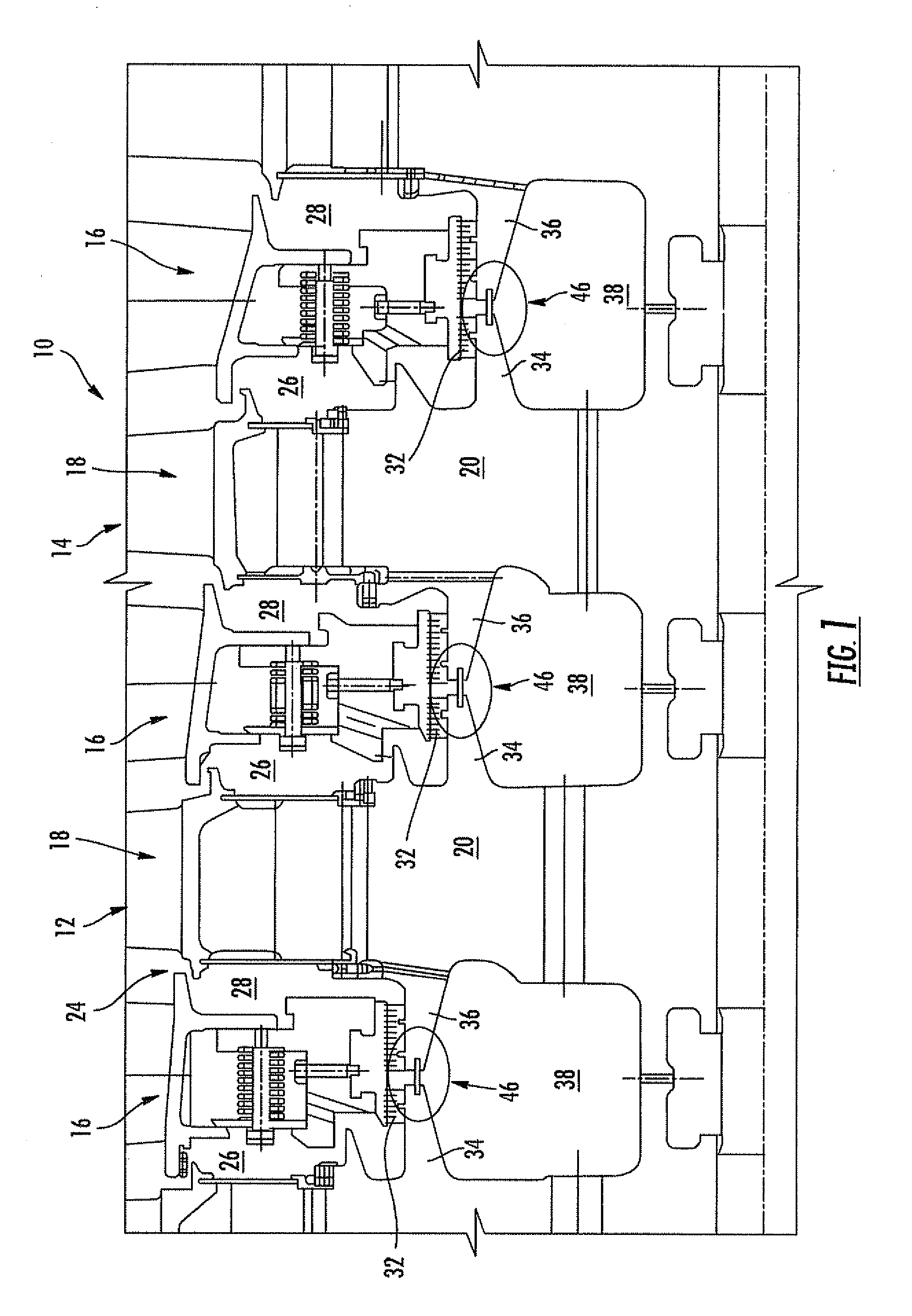
[0023]Referring initially to FIG. 1, a portion of a turbine engine 10 is illustrated diagrammatically including adjoining stages 12, 14, each stage 12, 14 comprising an array of stationary vane assemblies 16 and an array of rotating blades 18, where the vane assemblies 16 and blades 18 are positioned circumferentially within the engine 10 with alternating arrays of vane assemblies 16 and blades 18 loc...


PUM

PropertyMeasurementUnit
Angleaaaaaaaaaa

Abstract

The turbine includes a plurality of successive stages each having a rotatable disk and blades carried thereby. A pair of adjacent rotatable disks define an annular gap therebetween and have respective opposing sealing band receiving slots aligned with the annular gap. At least one of the rotatable disks has at least one notch therein coupled to the respective sealing band receiving slot, and a sealing band is in the opposing sealing band receiving slots to seal the corresponding annular gap. The sealing band includes at least one sealing strip and at least one movable locking tang carried thereby and extending into the at least one notch to define an anti-rotational feature for the sealing band.

Description

FIELD OF THE INVENTION[0001]The present invention relates to the field of turbines, and, more particularly, to baffle seals within a turbine and related methods.BACKGROUND OF THE INVENTION[0002]In various multistage turbomachines used for energy conversion, such as turbines, a fluid is used to produce rotational motion. In a gas turbine, for example, a gas is compressed through successive stages in a compressor and mixed with fuel in a combustor. The combination of gas and fuel is then ignited for generating combustion gases that are directed to turbine stages to produce the rotational motion. The turbine stages and compressor stages typically have stationary or non-rotary components, e.g. vane structures, that cooperate with rotatable components, e.g. rotor blades, for compressing and expanding the operational gases.[0003]The rotor blades are typically mounted to disks that are supported for rotation on a rotor shaft. Annular disk arms extend from opposed portions of adjoining disk...

Claims


Application Information

Patent Timeline
IPC IPC(8): F01D11/00B21K25/00
CPCF01D11/005Y10T29/49325F05D2260/30
Inventor NEREIM, BRIAN D.SHAEFER, DAVID M.
Owner SIEMENS ENERGY INC
Why Eureka
Try Eureka